A deep dive into Caustics in Octane for Cinema 4D
At some point in our lives, we have all noticed or created beautiful light patterns by moving a metal or glass object around a sunny room. These patterns are known as “caustics;” they are formed when light bounces off a reflective surface (or passes through a refractive one) and concentrates on a matte surface. Caustics require lots of calculations. It is one of the more difficult tasks we can assign to a GPU. In this post, let’s take a deep dive into Caustics in Octane for Cinema 4D. We will look at how Octane handles this phenomenon and the best method to set up our scene to obtain the most impact without spending the rest of our lives rendering.
I. Basics to get you up
What we need to get interesting visible caustic patterns:
-
-
- A piece of geometry with reflective or refractive material on it such as metal, glass, shiny plastic, etc., to cast caustics.
- A piece of geometry on which the caustic pattern will occur. The material used to cover this surface should be matte or rough. It can have some reflection, but not too much since it can degrade the effect.
- A light bouncing off our reflective (or through refractive) geometry onto the matte surface.
- Set the Octane kernel to Pathtracing, PMC, or Photon Tracing. If you are using Photon Tracing, you need to turn on the “allow caustics” checkbox on each material that casts caustics.
-
Next, set it up really quickly:
Step 1: Geometry
In a new scene, create a tube primitive, which is the caustics casting object. Make the outer radius 60, give it 100 rotation segments, position it +50 cm on Y, and turn on Slice in the Slice tab. This defaults to a slide with a perfect range of 0-180 degrees. Next, make a Plane object and set it to 1000x1000 cm for our caustic pattern to appear on.
Step 2: Materials
Next, use two materials. The first material is for the plane, thus it should be a matte dark gray. Let’s bring the Specular to 0, then change the Albedo to H:0, S:0, V:25%. We can load it into the plane now. The second material is the metal for the tube. Let’s set the Metallic to 1, and the Albedo Value to pure white – H:0, S:0, V=100%, and apply this on the tube. To allow the Photon Tracing kernel to cast caustics, we must click the “Allow caustics” box on the IOR tab.
Step 3: Lighting
This time, keep things simple using an Octane Area Light. In order for it to bounce off the inside of the tube and then hit the floor plane, set the Position coordinates to X:0, Y:300, Z:-300, and the Rotation.P to -45 degrees.
Step 4: Rendering
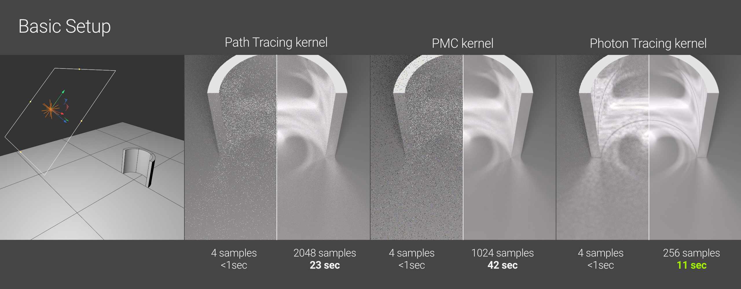
Set the kernel to Path Tracing, Max Samples to 2048, and GI Clamp to 10 for our render parameters. The earliest samples arrive as white speckles, but they eventually change to a heart-shaped Nephroid caustic pattern.
Though it is a little weak and grainy, we have caustics finally!
-
-
- When we use the PMC kernel, we need fewer samples to achieve a beautiful look, but it takes roughly twice as long to render half of the samples. It also takes more samples to resolve the caustic pattern, so unless we had a true beast of a workstation, lookdev tuning would take an eternity.
- Now, switch to the new Photon Tracing kernel and ensure that our metal material’s IOR tab has “allow caustics” checked. Within 4 samples, we notice that the caustics start to visibly resolve! Furthermore, it takes many fewer maximum samples to make it look beautiful. If you want caustics in Octane, this is the way to go most of the time in the future.
-
II. A deep dive into Caustics in Octane for Cinema 4D
The concentration part is the most interesting when trying to replicate Caustics in Octane. The concentration of the rays is essential to get the most visible caustic patterns. Four factors that affect this include the geometry of the casting object, materials, lighting, and render settings. Let’s dive into each factor.
1. Geometry
Knowing that we want light concentration, it’s clear that the shape of the casting object will be significant.
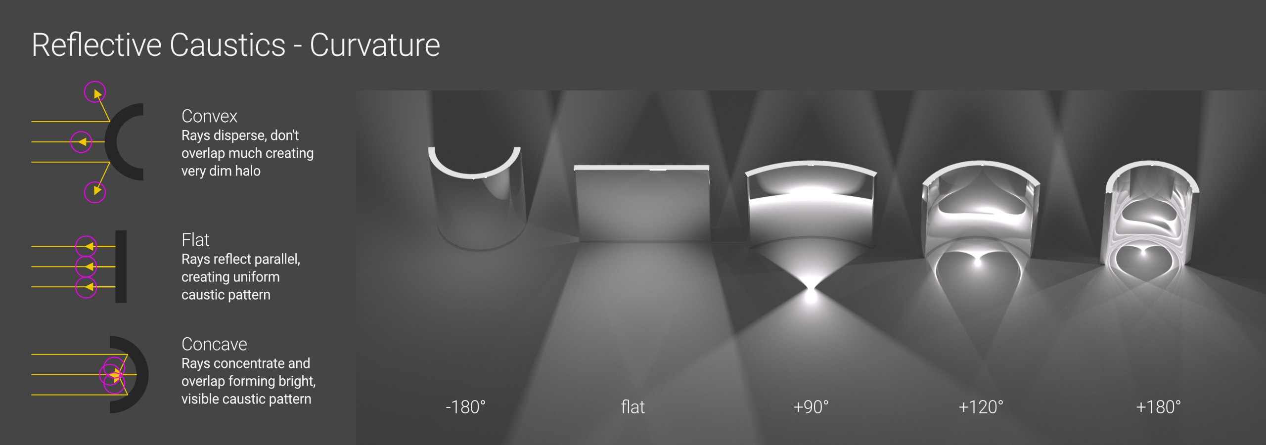
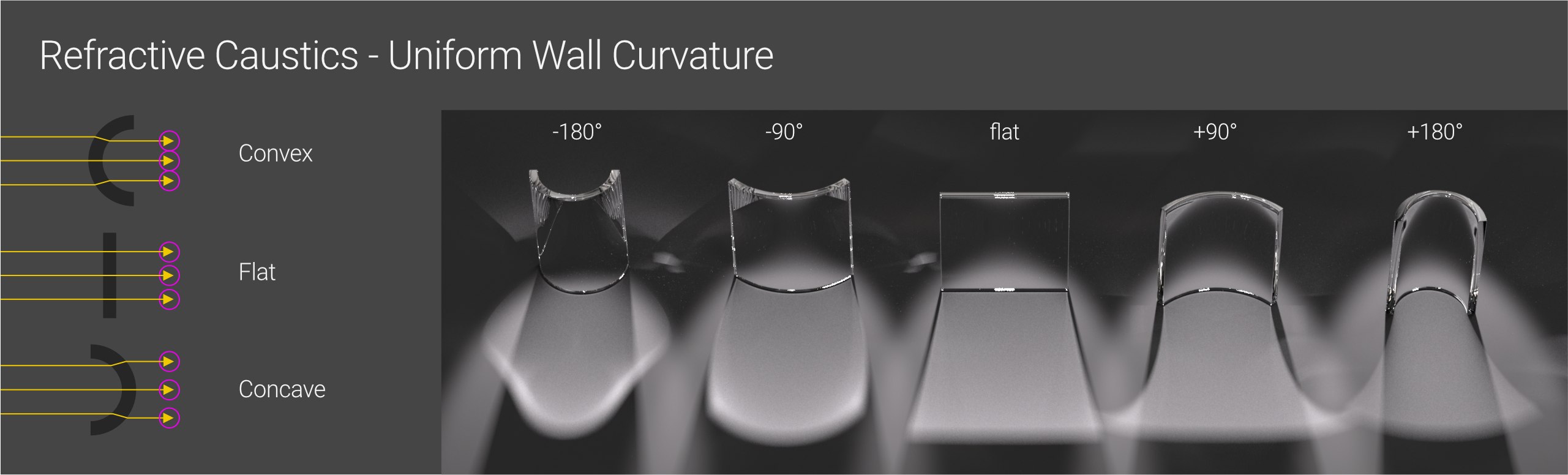
We can see above how, when using a reflective material (metal in this case), the more concave its shape becomes, the more light is concentrated, and the more complicated and visible the caustic pattern becomes as it builds up in a tighter area on the ground plane. Convex forms (far left shape) splay the light rays out, leaving only a weak glow at the object’s base. A perfectly flat mirror simply lights the ground plane and isn’t very interesting on its own. The 180-degree concave form (the far right shape) bounces light and creates an intricate nephroid pattern.
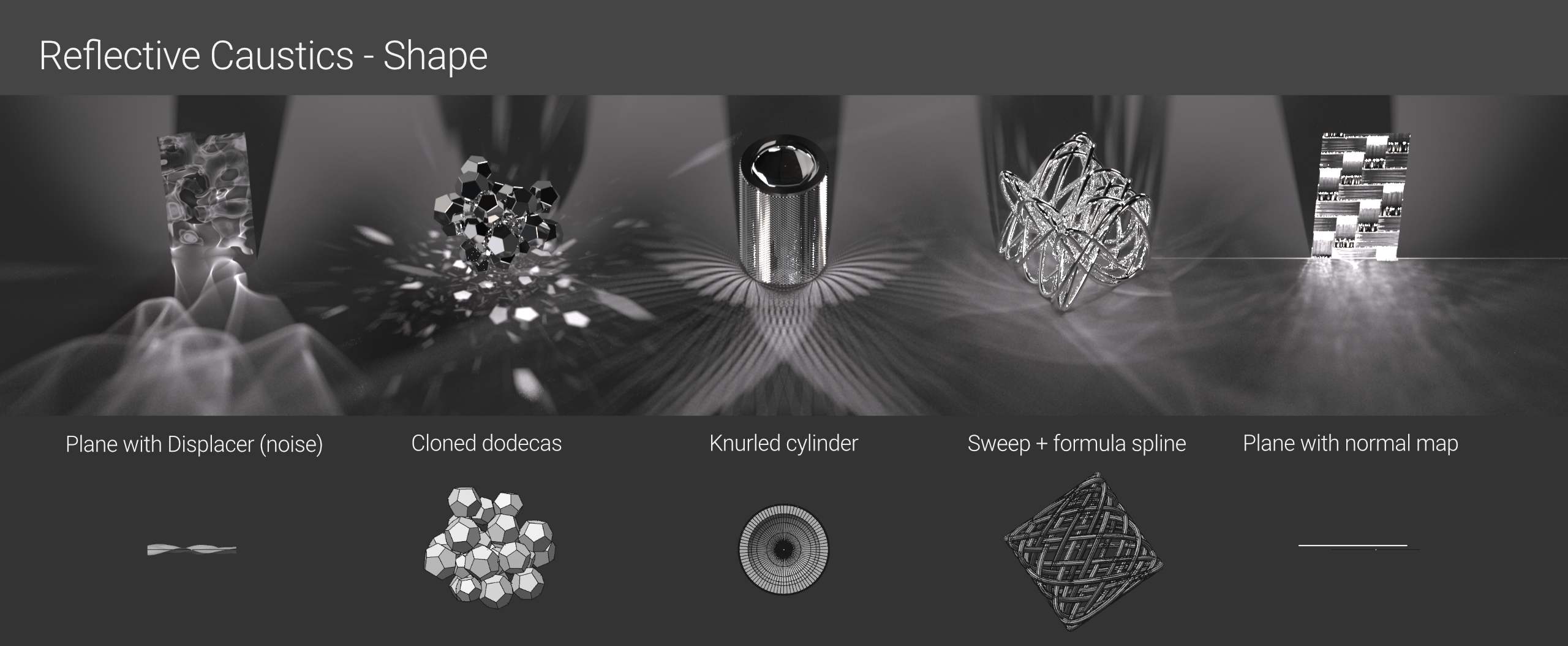
More complicated shapes create more complex patterns. The geometry doesn’t even have to curve; it only has to redirect the light, so we could use a flat plane with a bump or normal map (far right in the above image) or a lot of tiny angular pieces (the second shape from the left) to obtain an attractive pattern. The more curvature there is in the geometry, the smoother and more organic the caustic pattern will be.
Refractive caustics is far more difficult. There are significantly more calculations involved, making them more difficult to forecast and also more demanding on the GPU (resulting in longer render times).
If we use the same set of curved uniform cubes as in the reflective material example, we find that the light does not concentrate all that much regardless of how much it is curved. This is due to how optics works: with a uniform wall, the entrance and exit angles cancel each other out, so most rays continue to go in the same direction, and the resulting pattern is rather uniform and uninteresting.
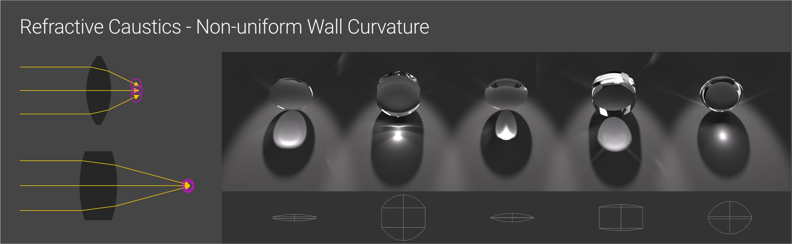
Because the entrance and exit angles in a convex lens compound rather than cancel each other out, the rays all angle in and focus the light, which is just what we want for great caustics.
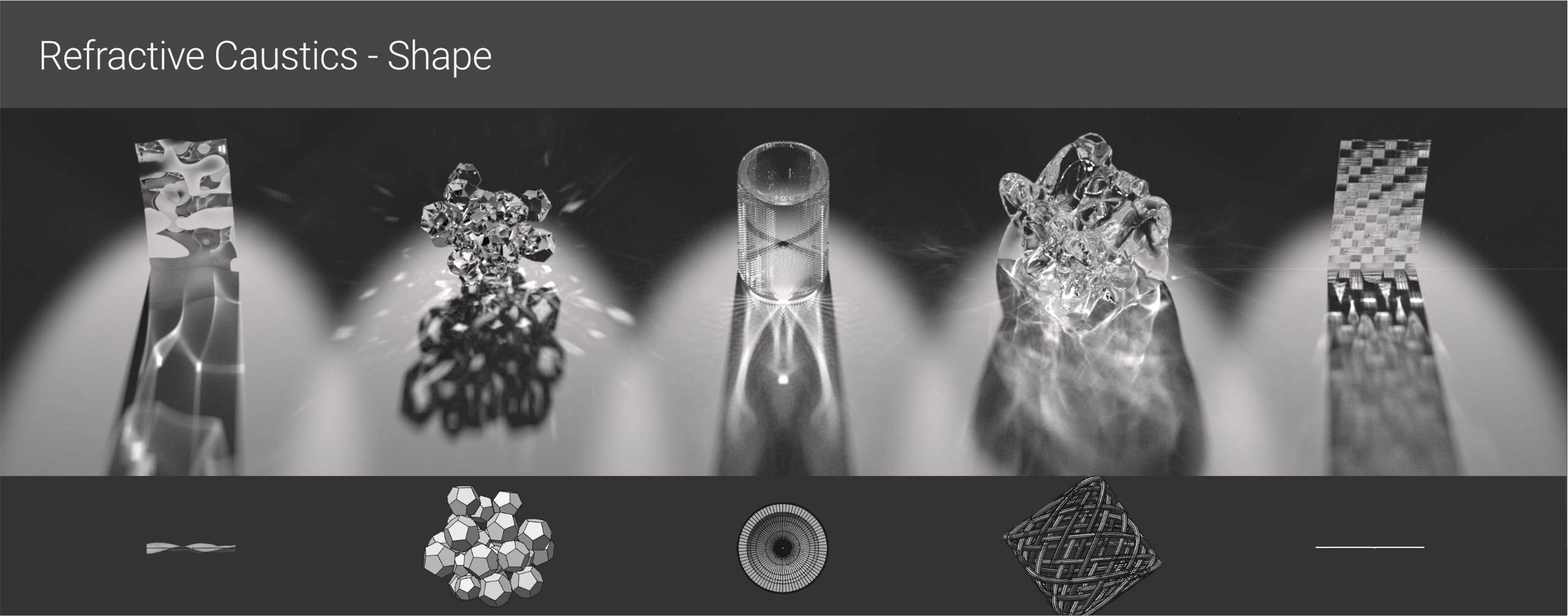
If we go a step further and make more complicated shapes, light will refract and concentrate in more attractive patterns. However, the IOR and light placement play an equal part in redirecting the rays. Let’s see the following Material and Light factors.
2. Materials
To achieve the brightest, sharpest caustics, our casting material should either reflect or transmit as much light as possible while our receiving material should reflect, transmit, and/or absorb as little light as possible. To control this, we need to look at a few properties.
2.1 Reflective Casting Material
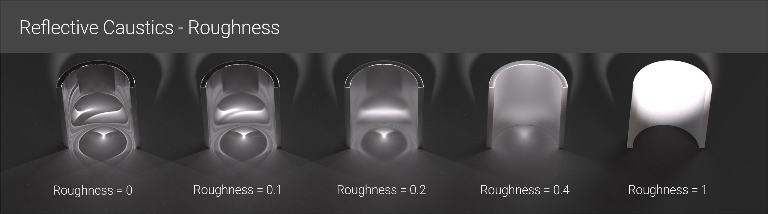
Roughness is the most simple property to understand. The rougher the reflective casting material, the more light rays it disperses and the blurrier and weaker the caustic pattern. Fine bump or normal maps have the same impact on roughness, thus we need to apply these carefully.
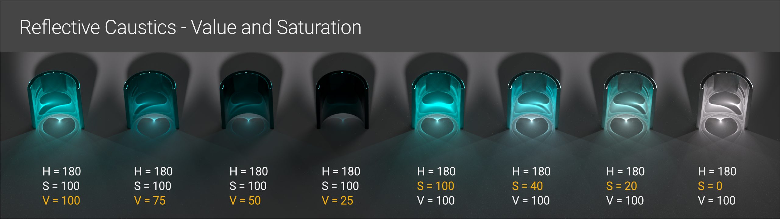
The color of the casting material is also crucial. Colors with a high Value (V) % reflect more light and generate better results when using the HSV color model. Lower Saturation (S) result in whiter overlapping areas that show out more against darker backgrounds.
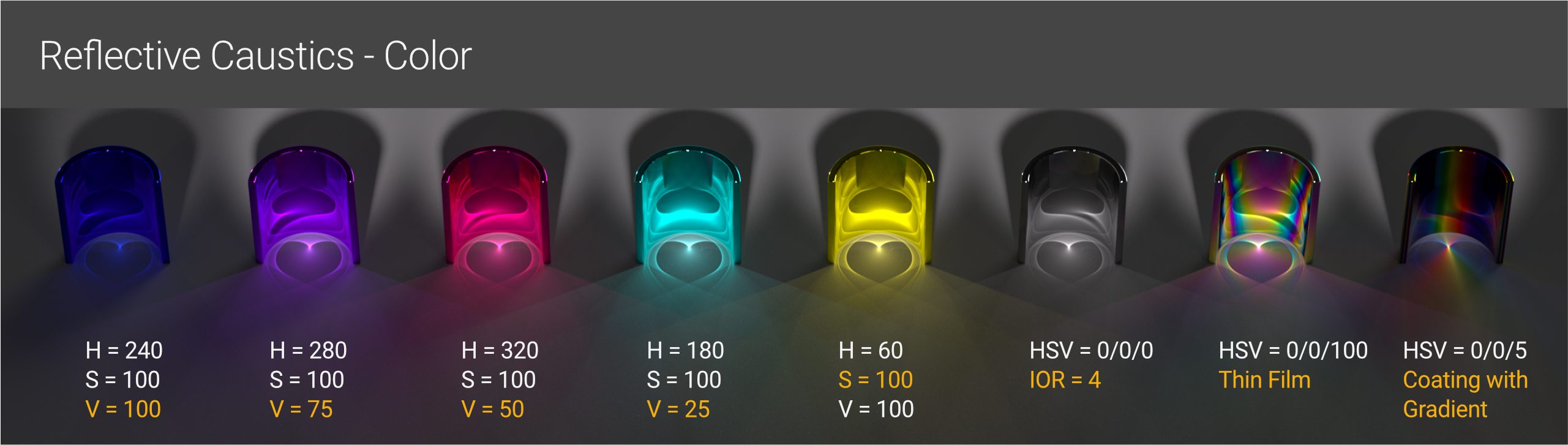
Certain hue colors (yellow/60°, cyan/180°, and magenta/320°) naturally reflect more light than others (red/0°, blue/240°, or violet/280°). As a result, we need to compensate with lower saturation levels and higher reflectivity (IOR) with darker hues. We can add variation by using Thin Film or a Coating layer driven by a gradient.
2.2 Refractive Casting Material
For good refractive caustics, we want as much unencumbered light passing through our geometry as possible. Roughness and base color have the same effects as reflecting materials in that the less roughness and lighter the color, the more light gets through and the brighter the patterns. Refraction is different from reflection in that we also have IOR and dispersion to contend with.
Important: In more recent versions of Octane, the Transmission channel’s default mode is Diffuse. For the greatest results, change this to Specular. Diffuse transmission will, well, diffuse the light rather than concentrating the rays into caustic patterns as we want.
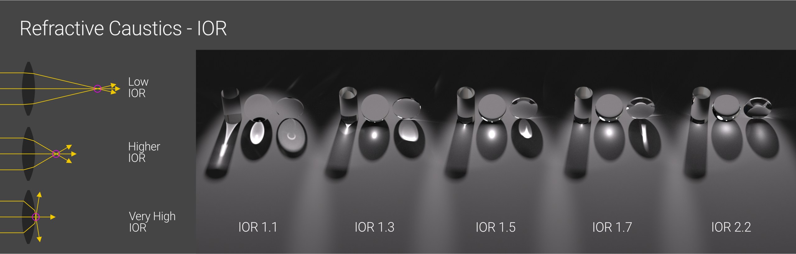
IOR is a balancing act involving geometry and light placement. In general, the lower the IOR, the less light bends and the further away the focus point. The path of the light is also influenced by the thickness of the geometry and angle at which the light hits the walls. When the IOR is too high, the focal point is so close that the rays going out the opposite side scatter, making the caustic pattern soft or difficult to see.
The IOR of air is 1.0, water is 1.3, normal glass is around 1.5, and the highest refractive IOR found easily in nature is 2.4, which is seen in gemstones such as diamonds. If sharp caustics are required at higher IORs, the wall thickness must usually be fairly thin, or the object must be faceted like a cut gem.
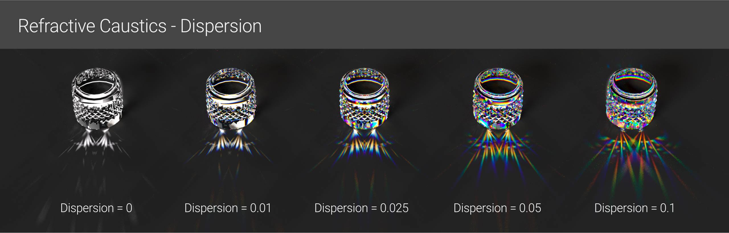
Dispersion is a natural phenomenon. It happens when visible light’s various wavelengths interact with a transmissive thing. This splitting causes various hues to arise, which then translate to the caustics, resulting in some quite stunning effects. Sharp geometry, such as prisms or cut jewels, will provide more distinct color splitting than soft, wavy geometry, such as a noise displacer.
Dispersion + Caustics is one of the most difficult things we can ask a GPU to accomplish. We’ll have to be patient while it calculates refraction, dispersion, and caustics. Higher values frequently slow down render time, and using 0.1 (the highest) frequently results in a lot of noise and artifacts requiring a ton of samples to clean up.
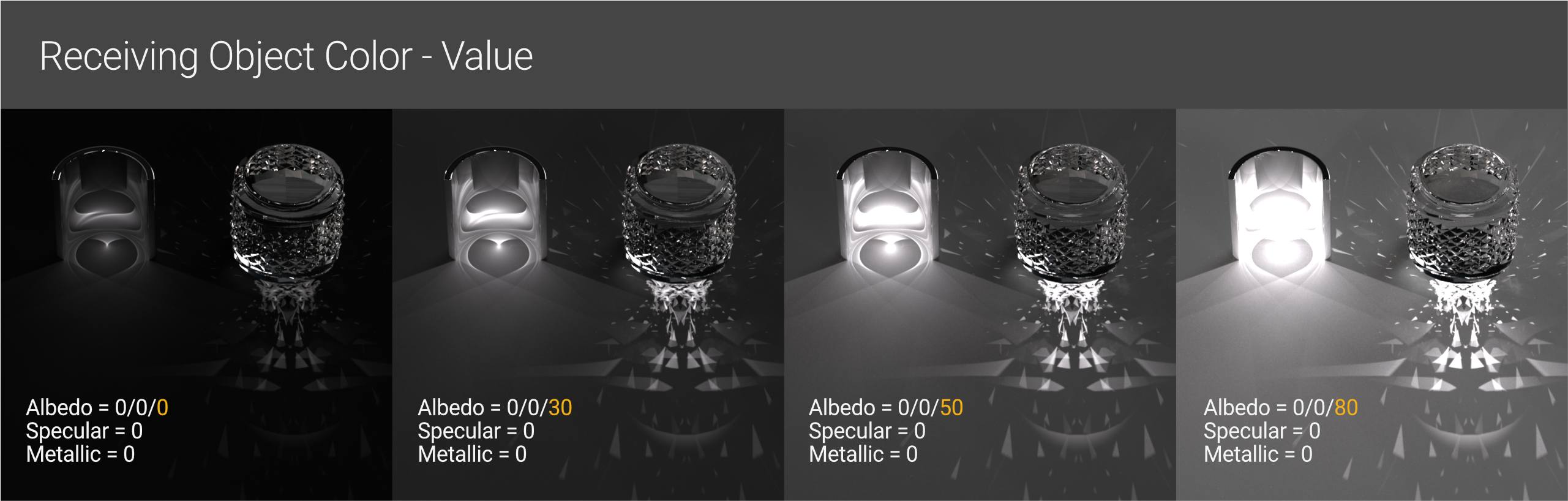
The base color should be reasonably dark and non-reflective (Albedo V (value) is ranging from 20 to 30, with Specular and Metallic channels set to 0 producing decent results). This will also modify as the light’s intensity varies. In general, the lighter the material on the receiving item, the more the caustic patterns are washed out. However, it cannot become too dark, or it will absorb all of the light, as seen on the far left in the above image.
In this case, a value of 30 is precisely about the sweet spot – black enough to contrast nicely, but not so dark that they are absorbed, or too bright that we lose details in the bright parts.
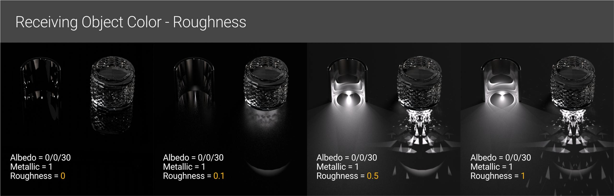
Reflection also reduces the effects of caustics by bouncing the light away and reflecting the original geometry, which may or may not be desirable. Roughening a metallic or high dielectric specular surface will help, but it must be fairly high to see the caustics sharpen (start with 0.5 and work your way up).
3. Light
In a word, we want relatively small, powerful bright lights that emit as many directible, parallel-ish rays as possible that we can bounce off (or through) our objects without washing out the resulting pattern.
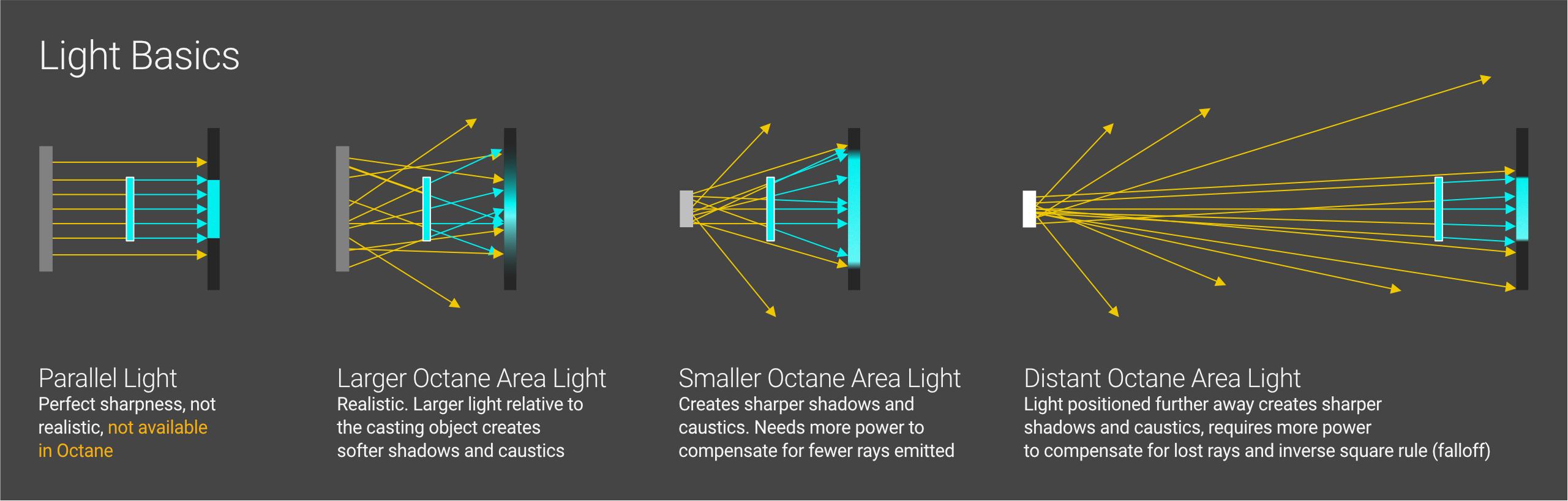
A parallel light would produce the sharpest possible shadows and caustics because all of the rays are released in the same direction. Because there is no real-world equivalent for this form of light, it does not exist in Octane. Light sources in the real world (and Octane) emit rays in all directions. Our goal is to have as many parallel-ish rays reflecting off or going through our casting object as possible. The curvature or the IOR/curvature of a refractive object can then focus these rays even further to provide us with sharp, clear caustics.
Rays that do not hit our object but instead hit the surrounding surface will look like normal illumination, and depending on the size and angle of the light, this can be quite bright.
So, how can we control the light rays if we can’t get a parallel light going?
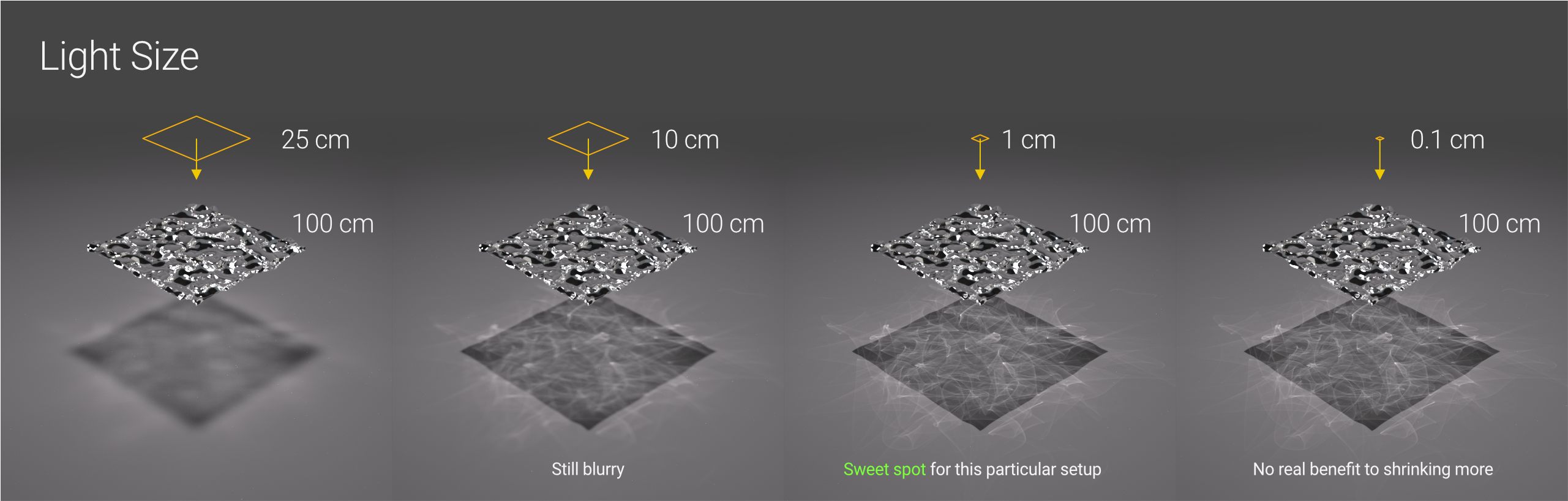
We can reduce the surface area of the light in comparison to our casting object. This means that fewer rays will hit our object, but those rays will be more parallel than in a larger light because the other, more sharply angled ones will simply miss it. If we use Surface Brightness, we must make the tiny light stronger than the larger one. A closer, smaller light will enlarge and distort the caustics/shadow area, which may or may not be okay. If caustics are a key goal of the render, one of the simplest methods to alter the sharpness is to change the size of the lights that impact the casting objects.
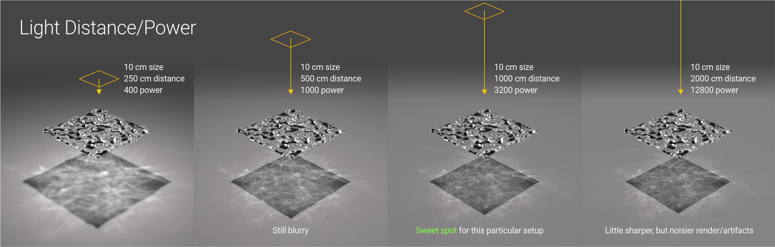
We can also shift the light away from the casting object. Because of the geometry and angles, fewer rays will hit the casting object, and we must now consider light falloff (running out of energy over the distance before hitting our object) and increase the power accordingly. The advantage of this is that the rays will be much more parallel, resulting in sharper and less distorted caustics and shadows. The disadvantage is that it takes a lot of tweaking to get it to focus properly. Unless the caustic pattern size is a problem, it is preferable to “focus” the caustics using the light size and material IOR.
3.1 Light Cancellation
One of the major problems with shining a bright light on a surface is that the light can muddy or wipe out the caustic pattern. There are a number of options for dealing with this, such as gobos, IES lights, and physically blocking rays with geometry, but a Spotlight Distribution node is a quick and straightforward approach we may consider.
At the time of writing, neither Octane nor C4D’s light linking works with caustics.
To get a spotlight distribution on an area light, simply click the Octane Light tag and navigate to the Light Settings. Click the small down-arrow icon next to Distribution, then select c4doctane, and finally Spotlight Distribution.
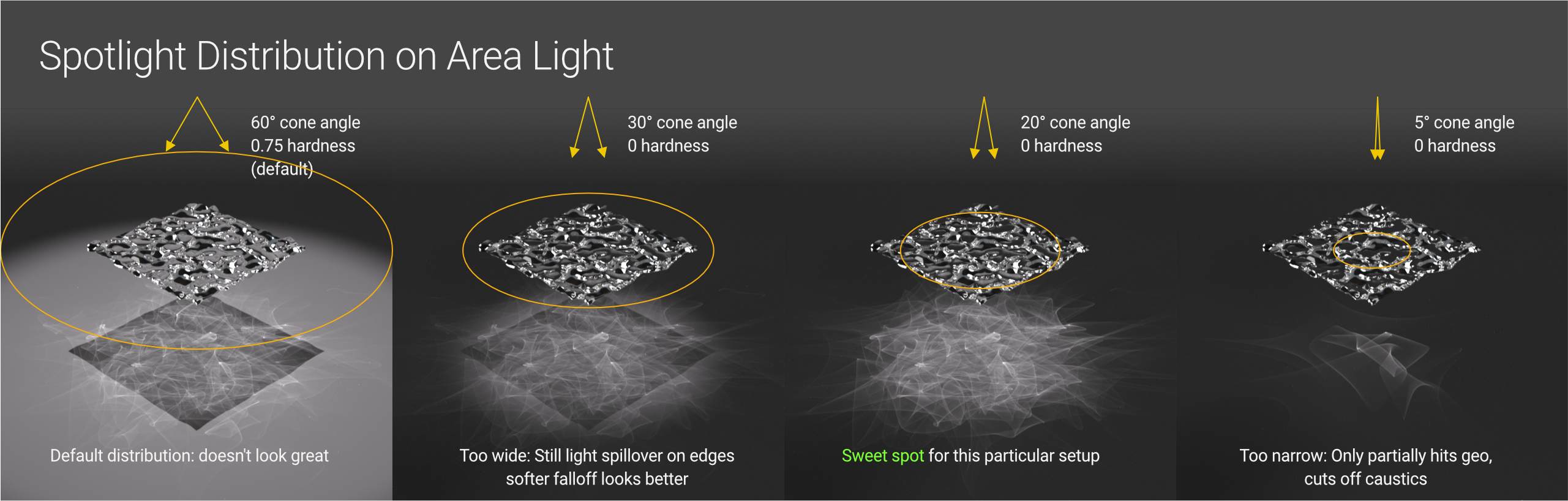
The two most essential values here are the Cone Angle and Hardness. They will differ based on the size of the light, the distance between the light and the casting object, and the shape of the casting object, so it will simply be a matter of experimenting till it looks nice.
4. Render Settings
The render settings are the final step in the caustics equation.
Caustics are generated by the Pathtracing, PMC, and Photon Tracing kernels. Pathtracing was once the quick way to generate okay-ish but denoise-able caustics, whereas PMC was the go-to for better-looking but GPU- and patience-taxing caustics. Octane’s most recent versions have added the Photon Tracing kernel, which is effectively a supercharged version of Pathtracing that outperforms the best aspects of both PT and PMC. In fact, it’s so much better that we’re skipping over the other two kernels in this guide.
Because many of the parameters are the same as in Pathtracing, we won’t go through them as thoroughly as the new Photon tracing-related settings.
The most important aspect to understand about caustics in Photon tracing is that it is material-driven. If we took into account all materials and objects in a scene when producing caustics, our computers would definitely catch fire, thus a line had to be placed somewhere so we could actually finish our renders.
Important: Only casting materials with the IOR channel option “Allow Caustics” checked will cast caustics in the Photon Tracing kernel. Fake Shadows must also be unchecked in the Common tab for it to work.
Now that we’ve gotten that out of the way, we can dig into the tweaky options.
4.1 Basic Photon Tracing Settings
The top section of the setting box looks a lot like Pathtracing.
Max samples still determine how many passes the kernel does to resolve the image. In general, more passes result in less noise. The beautiful thing about photon tracing is that we need FAR fewer samples to resolve caustics than PT or PMC, so we can really get away with 256 or 512 while doing lookdev, which is incredible.
Although Diffuse, Specular, and Scatter depth have no effect on caustics, they must be considered for the appearance of the objects themselves.
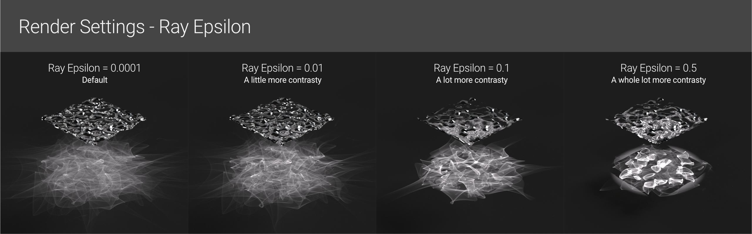
Ray epsilon does have an effect on caustics, however, it should be avoided most of the time. Keeping it as low as possible (the default is 0.0001) is ideal for realism, but we may start increasing it by orders of magnitude to get different creative effects.
Although GI clamp has no direct effect on caustics, it does have an effect on other GI-related light in the scene. A reasonable default for this is 10, and if the scene is mostly caustics, try setting it to 1 and seeing if the render cleans up faster.
Caustic-specific settings
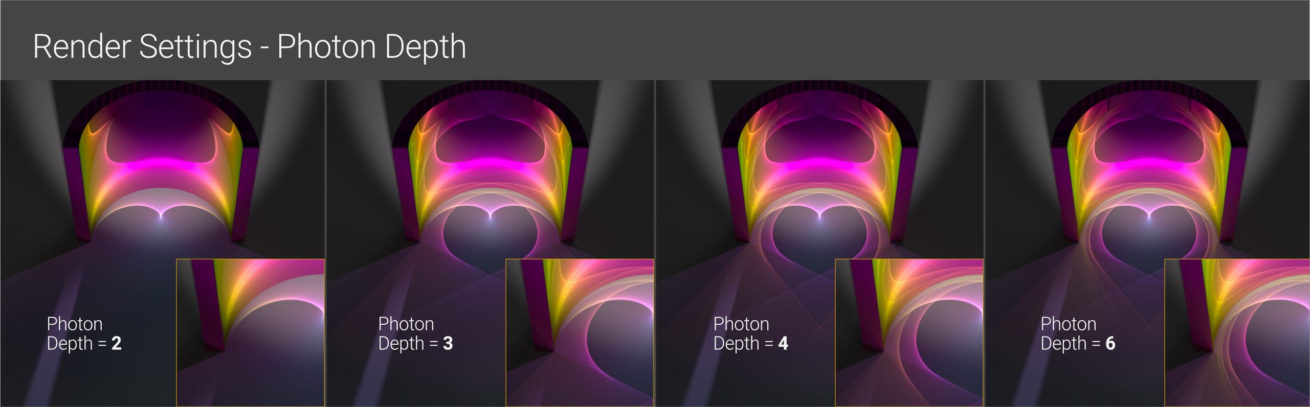
Photon depth: Similar to Diffuse/Specular/Scatter depth, this refers to how many times photons will bounce through different materials until they become extinct. For the most part, we may leave it at (6), but if we have a lot of panes of glass or multiple mirrors in a scene, we’ll want to increase it. It has little effect on render speed, so we’d only want to reduce it if we’re getting wild caustics that we don’t want for visual reasons.
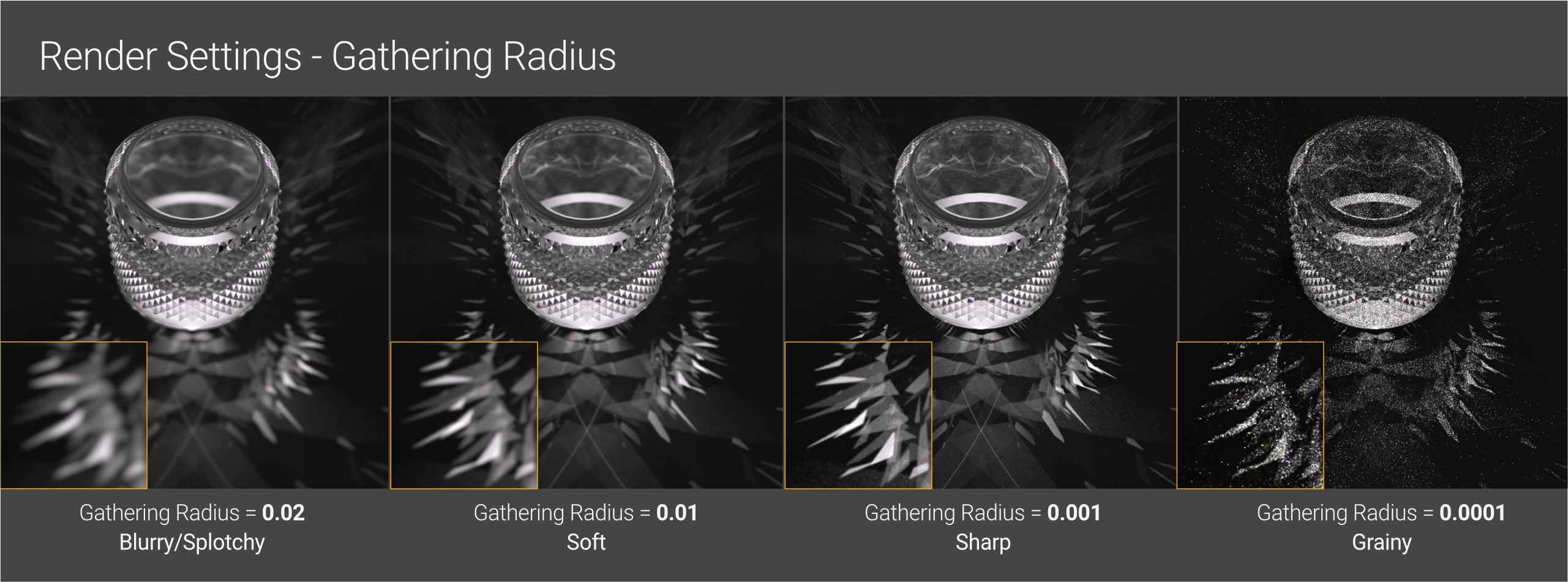
The Photon gathering radius is the most necessary caustic-related setting. It’s basically the photon resolution. The higher the value, the smoother/softer the caustics will resolve; too high, and it will become fuzzy. The smaller this value, the sharper the image and the caustics will be; too low, and graininess and artifacts may develop. It’s an act of balance.
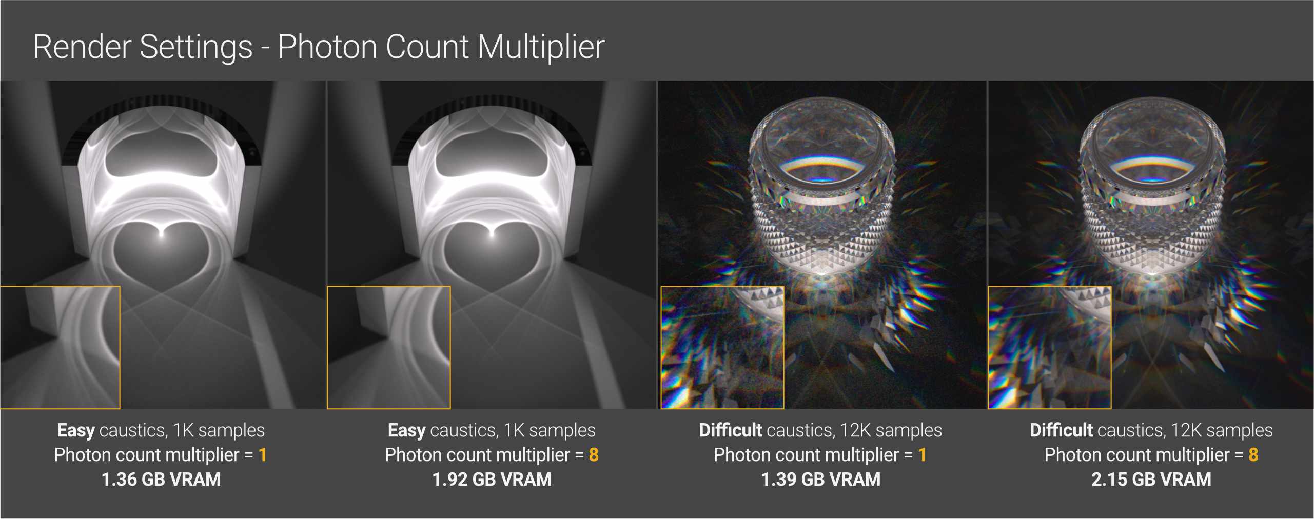
The Photon Count Multiplier acts as a bias slider for how much emphasis Octane places on caustics over other path tracing calculations. Given infinite time and samples, it wouldn’t matter whether this was set to 1 or 8 – everything would eventually resolve roughly the same, but we don’t have time for infinite samples right now, so we need to guide Octane’s efforts.
As a general rule, if the scene has simple caustics (one light source, reflective material, or mild caustics that aren’t a major component of the scene), the default of 2 will serve, and more emphasis is placed on making the rest of the scene seem better quickly. If the scene is all about the caustics, with crazy, jagged patterns, refraction, and dispersion, and the GPU is huddled in the corner, crying out, set this to 8 if you have the VRAM for it.
Setting it to 8 during lookdev is also a useful technique to resolve caustics faster, allowing for faster light/material/etc. tweaking. Once everything is in place, you can return to work on the rest of the scene.
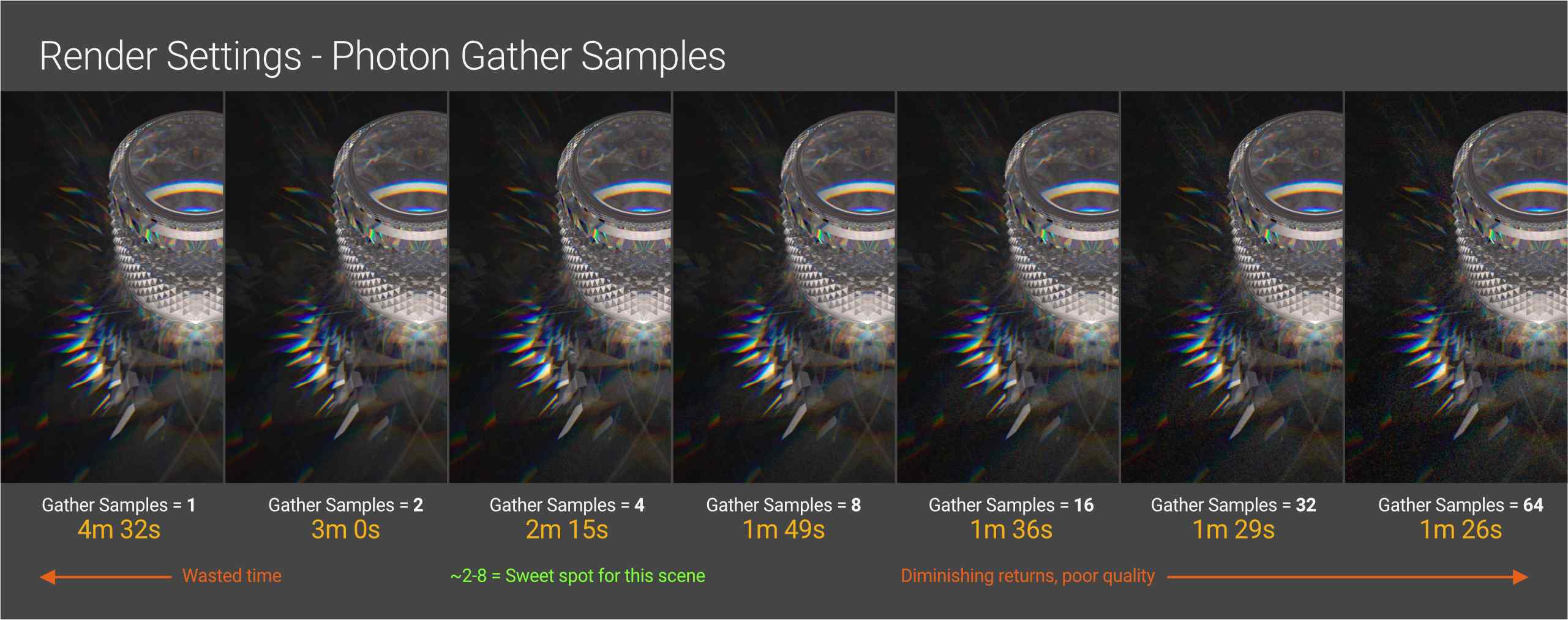
Photon Gather Samples – depending on the scene’s structure and noise tolerance, this can significantly speed up caustics renders. For the example above, 2 (default) delivers decent quality at a reasonable render time given the hardware, use case, size, and so on. When the gather samples are increased to 4, the render time is virtually cut in half, which is fantastic for lookdev, but it introduces some noise, which may or may not be acceptable. As the number of samples increases, the noise increases dramatically while the render times just slightly improve. The trick is to locate the sweet spot for lookdev and then the final render. (8 and 2 for this scene, respectively).
Photon Exploration Strength – this should be left alone most of the time, but if there’s a small amount of noise that won’t go away, increasing this to 1 may help at the expense of some render time. Setting it to 0 can also result in some fascinating aesthetic effects.
4.2 Denoising
Denoising caustics follows the same rules as anything else in a render. The denoiser works best when the forms are larger, smoother, and more organic. Sharp, detailed renders with tight patterns can be ruined if not enough samples are thrown at the initial render before denoising.
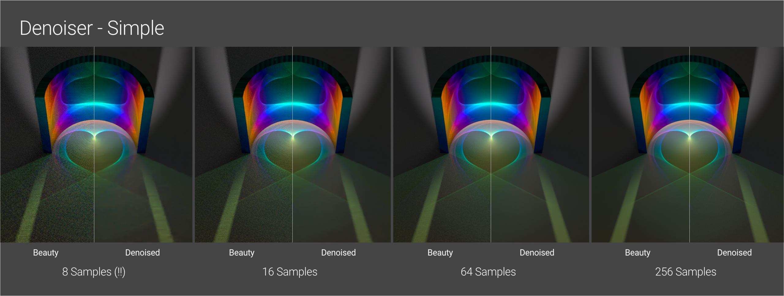
In a simple reflective arrangement like the one above, we can see that it performs admirably, even at 8 samples. For this scene, 64 or 256 is certainly better, but we have a lot of leeway. Everything is neatly smoothed out by the denoiser.
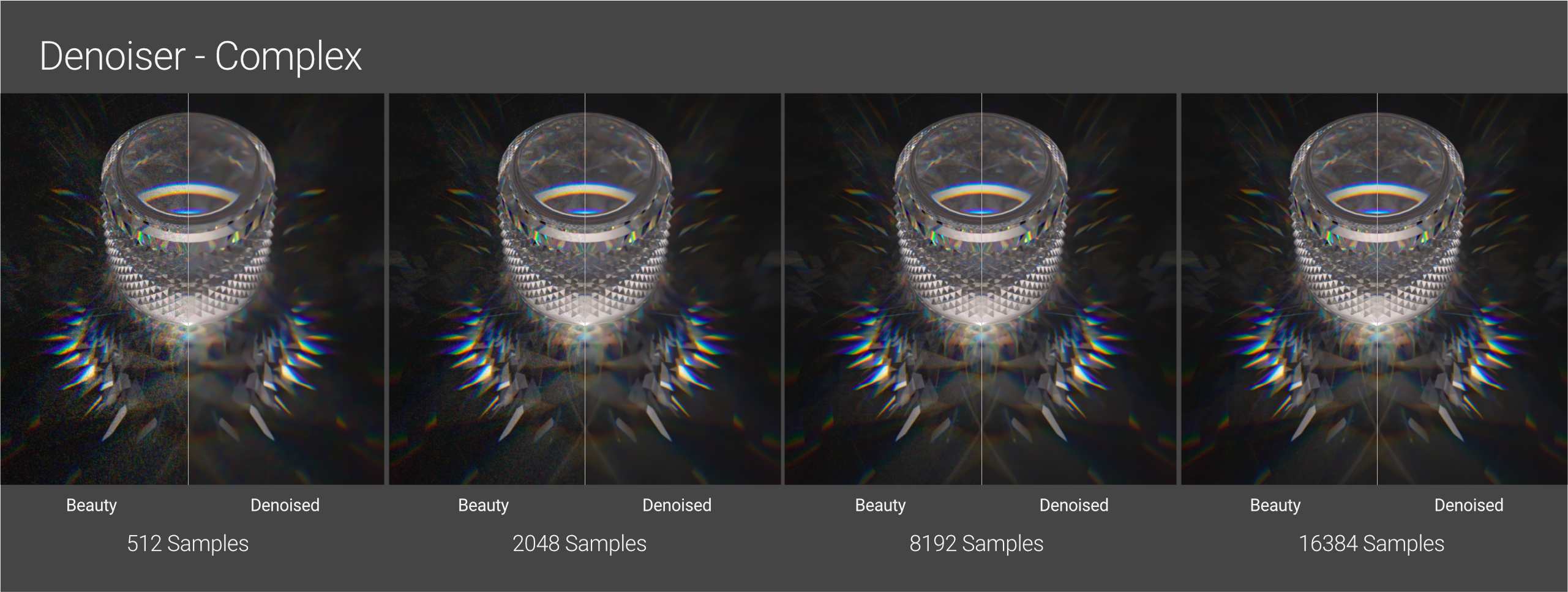
In a complex setup like this, we have noticed that the denoiser eats away the fine caustic patterns (particularly in the center right at the base of the cylinder and also on the back wall of it). It is not until we reach the 8192 range that it becomes suitable for final output.
Path Term Power, Coherent Ratio, and Adaptive Sampling are the same as they are in Pathtracing.
-
-
- Path Term Power is useful if there is a lot of noise in the render’s darker parts. We can reduce this to help clear up some of that. We can also increase it to speed up the render but add more noise in darker parts- if the render has no dark parts, this may not be necessary.
- Coherent Ratio can also significantly speed up the render, but there will be a lot of noise and artifacts unless the maximum sample count is set extremely high. This is particularly difficult with animation.
- Adaptive Sampling has its own procedure and is outside the scope of this guidance, but it does work with Photon Tracing.
-
Hopefully, you now have a much better understanding of caustics in Octane and Octane’s new Photon Tracer kernel. This is one of the most challenging tasks for a render engine, thereby mastering it will require time and patience. But it was well worth it!
III. Speed up Octane rendering with iRender
iRender provides high-configuration single and multi-GPU servers, specifically 1/2/4/6/8x RTX 4090 & RTX 3090. Powered with two of the most single-core performance CPUs for Octane which are AMD Ryzen™ Threadripper™ PRO 3955WX @ 3.9 – 4.2GHz & AMD Ryzen™ Threadripper™ PRO 5975WX @ 3.6 – 4.5GHz, 256GB RAM and 2T NVMe SSD storage, all our servers can work well with almost all levels of complexity of Octane projects.

iRender gives you, all creative individuals and studios, an affordable answer to unleashing your creativity with the beast RTX 4090 from just 8.2 USD/hour. We are proud to be the only render farm where you can install any software and plugins of any version that serves your project. You will be given complete control over the server(s) and use them as your local computers.
Let’s check out our test videos about Octane rendering performance on our 6x RTX 4090 beast.

Get a FREE TRIAL to try our RTX 4090 machines. And don’t forget to enjoy our 4th birthday’s gift.

For further information, please do not hesitate to reach us at [email protected] or mobile: +84915875500.
iRender – Thank you & Happy Rendering!
Reference sources: Scott Benson on otoy.com
Related Posts
The latest creative news from Octane Cloud Rendering.