Advanced techniques to boost render speed on Redshift 3D
Redshift is a powerful GPU-accelerated renderer, built to meet the specific demands of contemporary high-end production rendering. In other words, Redshift 3D is tailored to support creative individuals and studios of every size. In fact, Redshift offers a suite of powerful features and integrates with industry-standard CG applications. Over the past few years, more and more designers are using Redshift for rendering and dramatically speeding up their render times thanks to this renderer.
And amazingly, Redshift 3D has various options that allow you to fine-tune the performance of rendering, depending on your scene requirements. For today’s article, let’s go with iRender to explore some best Optimization techniques to boost render speed on Redshift 3D.
1. Maximum Trace Depth
The trace depth limits control how deep reflections and refractions can go. There exist separate settings for reflection, refraction and transparency. The “combined” setting specifies the upper limit for both reflections and refractions. Let’s say, for example, that reflection, refraction and combined are all set to a value of 10. If a ray has already been reflected 8 times, then it can only be reflected or refracted 2 more times because the combined trace depth is 10. The transparency trace depth allows straight transparencies like Opacity in the Redshift Material to go much deeper than complex refractions. The Transparency Trace Depth setting was added with Redshift 3.0, when using RS 3.0 to match results with older scenes, please make sure to set the Transparency Trace Depth to the same value as the Refraction Trace Depth to get similar results as 2.6, with regards to both look and performance.
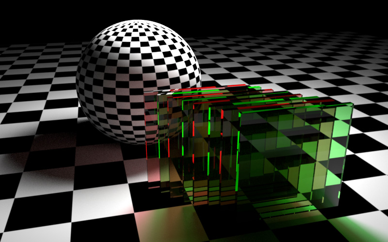
Note that Raising the trace depth limits can increase rendering times! Most scenes can get away with fairly low reflection and refraction trace depth limits. This is especially true for reflections. How often can you see a reflection of another reflection of another reflection… and so on? Refractions, on the other hand, can be more challenging. Scenes that contain glass might require the refraction trace depth limit to be raised to avoid incorrect results behind a few layers of glass, as shown below:
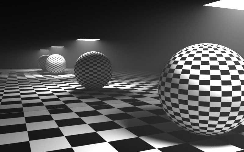
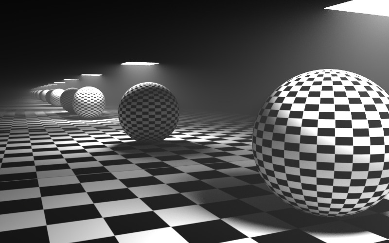
Similarly, an “opposing mirrors” scene like the one shown below will require the reflection trace depth limit raised.
2. Cut-off Thresholds
As rays go through reflections, refractions or shadows, they get tinted and become dimmer. For example, a ray coming from the camera might hit a very faint mirror. Whatever is reflected on that mirror will be dim. When the rays become dim, they contribute very little to the final image so there is no point for the renderer to keep bouncing them around.
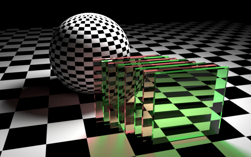
The Cut-off threshold set of parameters allow the user to specify minimum values that are considered “black” and allow the renderer to terminate tracing earlier. The defaults should work fine for most scenes but, in some extreme cases, a very dark mirror might be reflecting an extremely bright piece of geometry. If the renderer “cuts off” the mirrored rays early, grain will appear. If you suspect this is happening to your scene, you can try lowering these numbers. To disable this optimization altogether, set the values to 0.0.
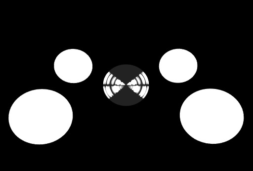
The test scene below shows what happens if there are very bright objects in the scene and the cutoff thresholds are not low enough. In the middle of the scene there is a glass reflective and refractive sphere. Around it are 4 very bright self-illuminating spheres. The reflection and refraction trace depths are set to 16 so the reflections/refractions of the self-illuminating spheres ‘repeat’ many times inside the glass sphere.


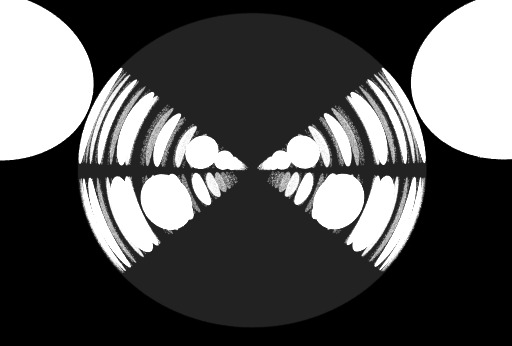

3. Russian-Roulette
Certain shaders need to shoot multiple different kinds of rays. For example, a glass shader needs to shoot a ray for reflection and another one for refraction. The architectural shader can shoot two reflection rays (with different gloss values) and one refraction ray. The car paint shader shoots two reflection rays (with different gloss values). When the rays of such shaders ‘see’ other shaders of the same kind, the number of rays that have to be shot can grow exponentially with increasing trace depths. The initial two rays of a glass shader might become 4 rays on the next trace depth, then 8, then 16, 32, 64, and so on.
Russian-Roulette allows the renderer to shoot only one kind of ray once the importance of the ray is low. For example, a glass seen through a very faint mirror can often get away with sometimes shooting a reflection ray and some other times shooting a refraction ray. Choosing which kind of ray to shoot (reflection or refraction) is driven by shader parameters. If a glass, for example, is very transparent and only has a very faint amount of reflection, the renderer will mostly choose refractive rays versus reflective ones.
The “Importance Threshold” decides when the renderer will start performing this optimization. Very low numbers mean “start doing it for very dim rays” while higher numbers mean “do it for slightly brighter rays”. So the higher the number, the earlier the optimization will happen. Starting it too early, though, can introduce grain artifacts. If you see grain in your glass and you are suspecting the Russian-Roulette, you can try lowering this number to 0.001. To disable this optimization completely, set it to 0.0.
The “Falloff” parameter ‘eases’ into the Russian-Roulette optimization. This means that once a ray’s intensity crosses the “Importance Threshold” value the renderer won’t go abruptly into Russian Roulette but will do it gradually. This improves potential noise-banding artifacts. How gradually the renderer will ease into Russian-Roulette optimization is controlled by the “Falloff” parameter. Setting this parameter to 0.0 will enable the optimization abruptly, while 1.0 does it very smoothly. It’s very rare that users will need to adjust this parameter, so it’s advised you leave it at 0.5.
To demonstrate the Russian-roulette parameters, we’ll use the same scene we used for the cut-offs.

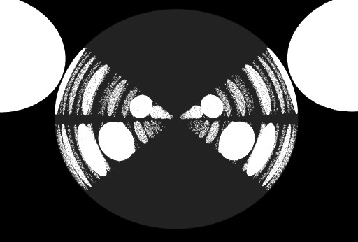


4. Texture Sampling
Redshift supports high quality texture mapping via ‘Anisotropic’ filtering. Redshift 3D also supports fast but lower quality texture mapping techniques such as ‘Bilinear’ (blurry) and ‘Point’ (blocky).
Most scenes only need high-quality texture mapping for parts of the image that are directly visible to the camera, i.e. the “primary rays”. Secondary rays (reflections, refractions, GI, lights) and shadow rays are often less visually important so they can get away with using lower-quality texture sampling techniques. For this reason, by default, Redshift enables ‘Anisotropic’ for primary rays and ‘Bilinear’ for secondary and shadow rays.
MIP-maps are pre-filtered (blurred) versions of the textures and are automatically computed by Redshift behind the scenes. MIP-maps are useful in making textures appear less noisy when viewed from far away. Each texture has several MIP-maps associated with it. For example, a 1024×1024 texture will have a 512×512, 256×256, 128×128, 64×64, 32×32, 16×16, 8×8, 4×4, 2×2 and 1×1 MIP maps. Each time the renderer needs to pick a samples for texture mapping, it selects two consecutive MIP-maps (for example 256×256 and 128×128) depending on how far away the textured object is from the camera and then filters in-between them. The best filtering for this job is called “tri-linear interpolation”. The “MIP Filtering Trace Depth Threshold” forces the renderer to disable “tri-linear” filtering between MIP-map levels after a specified trace depth, which will help performance but at the potential cost of introducing banding artifacts. Generally, banding artifacts will not be visible beyond certain trace depths, so it is recommended that you use the default settings and allow the renderer to use switch to “bi-linear” filtering after the first trace depth.
The “Copy Pre-Converted Textures to Cache Folder” option is used in junction with textures that have been pre-converted using the ‘TextureProcessor’ tool. By default this option is enabled, the assumption being that the local texture cache folder has better IO performance than the source texture folder, which is common for example when source textures are stored on slower network drives or when the local texture cache folder is on an SSD drive while the source texture folder is on a mechanical drive. By copying the pre-converted textures to the local machine cache folder, the out-of-core texture file streaming during rendering can be significantly faster, which can have a significant impact on rendering performance. This option should be disabled when the IO performance of the texture cache folder is equal to or lower than that of the source texture folder.
5. Global Overrides
The “Enable Reflections” and “Enable Refractions” options globally enable/disable reflections and refractions respectively. The “Enable Subsurface Scattering” option bypasses all subsurface scattering preprocessing and renders the SSS shaders as diffuse. Similarly, “Enable Tessellation And Displacement” enables/disables all tessellation and displacement. The “Enable Emission” option globally enables/disables emission on materials.
Conclusion
Hope that after this article, you can have better understanding of some advanced optimization techniques on Redshift 3D and can take advantage of them to create wonderful projects in the future.
One interesting thing for you! iRender is a Professional GPU-Acceleration Cloud Rendering Service provider high performance machines for rendering tasks, CGI, VFX with over 20.000 customers and being appreciated in many global rankings ( e.g: CGDirector, Lumion Official, Radarrender, InspirationTuts CAD, All3DP). We are proud that we are one of the few render farms that support all software and all versions. Users will remotely connect to our server, install their software only one time and easily do any intensive tasks like using their local computers. Redshift 3D users can easily choose their machine configuration from recommended system requirements to high-end options, which suit all your project demands and will speed up your rendering process many times.
High-end hardware configuration
- Offering the most powerful graphic card currently, RTX 3090. The servers range from Single and Multi-GPU servers: 1/2/4/6/8 x RTX 3090 with 24 GB vRAM capacity, fitting to the heaviest images and scenes. NVLink/SLI requested for bigger vRAM.
- A RAM capacity of 128/256 GB.
- Storage (NVMe SSD): 512GB/1TB.
- Intel Xeon W-2245 or AMD Ryzen Threadripper Pro 3955WX CPU with a high clock speed of 3.90GHz.
- Additionally, iRender provides NVLink (Request) which will help you increase the amount of VRAM to 48GB. This is a technology co-developed by Nvidia and IBM with the aim of expanding the data bandwidth between the GPU and CPU 5 to 12 times faster than the PCI Express interface. These servers are sure to satisfy Blender artists/ studios with very complex and large scenes.
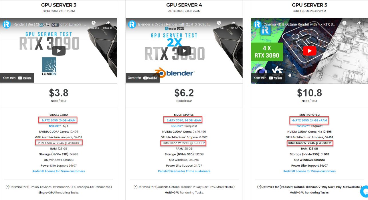
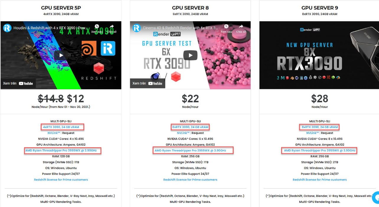
Let’s see rendering tests with Redshift 3D on multi-GPU at iRender:


If you have any questions, please do not hesitate to reach us at any time. Register an ACCOUNT today and get FREE COUPON to experience our service. We are availabe 24/7 to support you!
Thank you & Happy Rendering!
Source:Redshift documentation
Related Posts
The latest creative news from Redshift Cloud Rendering.