
Understand Mixing and Layering Systems in Octane for C4D (part 1)
This article is a step-by-step walkthrough that takes you through several strategies when choosing how to mix and layer materials and textures. As we all know, Octane has several ways of layering textures and materials together to form complex looks. This guide will walk you through how to use the most common ones by texturing a sci-fi crate.
There’s a lot of overlap and many ways to accomplish the same task in Octane. The goal of this step-through is to introduce you to as many layering and mixing systems in Octane as possible over the course of one project and then let you decide which ones you think will work the best in any future projects you make.
Let’s explore to understand Mixing and Layering Systems in Octane for Cinema 4D (Part 1).
Overview
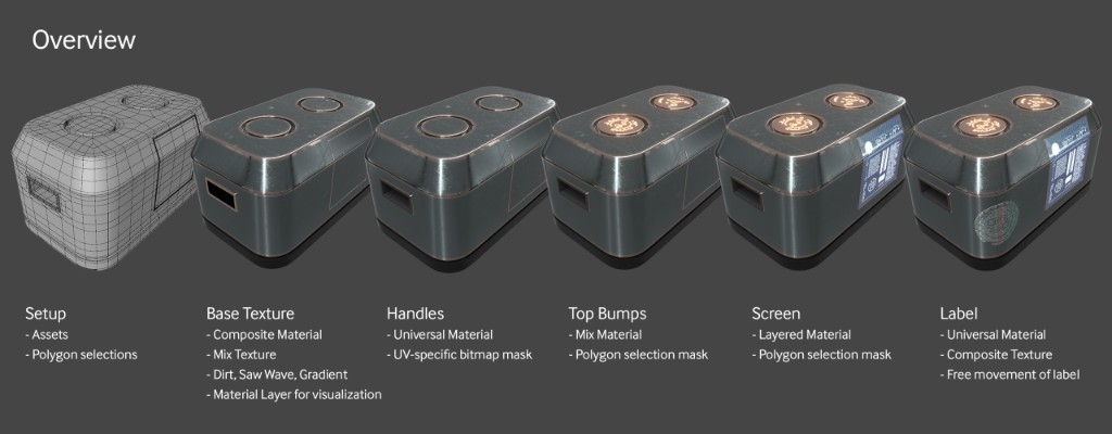
Let’s have a quick look at what we’re going to do and what we’ll cover:
- Setup: how the C4D file is constructed and point out where the assets originate from.
- Base Texture: We’ll build a Composite Material and set up a procedural mask using a Saw Wave, Gradient and Mix Texture node to tell Octane where to apply two different scratch masks. We’ll also be using a Dirt Node to apply some edge wear, touching on grouping nodes to clean up the node graph. Finally, we’ll reuse our procedural mask to restrict a rubber material to the bottom.
- Masking Strategies: Touch on UV mapping, polygon selections, and UV map-specific bitmap masks to discuss how to apply different masks to the various parts of the model.
- Handles: Use a Universal Material with a UV-specific bitmap mask in the opacity channel to apply a rubber material just to the handle areas of the crate.
- Top Bumps: Two Mix Materials will be used to show off how that system works and why it’s still relevant in Octane for Cinema 4D. We’ll use polygon selections here to mask off the areas of the crate we want these materials to appear in.
- Screen: Have a look at the Layered Material and how Material Layers work for the screen. The masking here will be done with polygon selections.
- The Label: The label will also be a Universal Material with an Alpha channel, but it’ll make use of the new Composite Texture node to add and subtract portions of the mask.
Setup
First, we’ll need some assets to get started. These come from HDRI Haven, CC0 Textures, JSplacement, and the rest are custom assets built from scratch for this tutorial.
Geometry
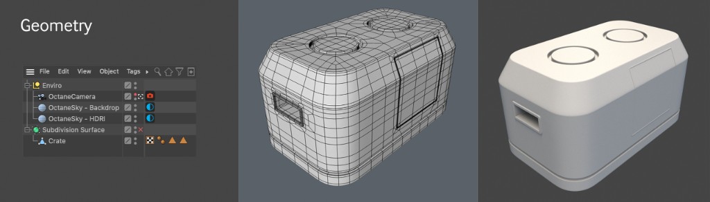
For this exercise, we’re going to use a fairly simple sci-fi crate mesh. This crate was modeled using subdivision surfaces techniques so that the UV mapping is easier to understand. The scene has the Adams Place Bridge HDRI from hdrihaven.com (desaturated) for reflections, and the backplate is overridden by a neutral gray color so it’s not distracting. Moreover, it also has three polygon selections (the little triangle tags on the Crate mesh) – one for each of the cylindrical bumps on the top, and one for the screen. We’ll be using those to restrict materials to just those areas.
The Base Texture
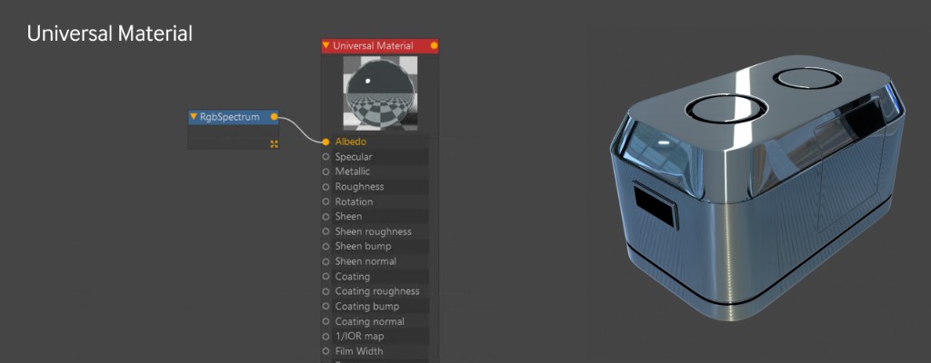
We’re going to start simple with a Universal Material (the material of champions™).
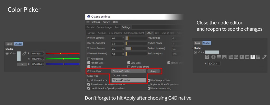
Let’s give it a nice medium steely blue color like #B2C0C3. Rather than embed this value, let’s use an external RGB Spectrum node so we can change it or mix it later. In C4D the color picker defaults to Octane’s 0-1 RGB system. If you click the little white square (the color preview) you can get access to HSV, Hex, etc, or you can choose a default color picker in the settings.
Building a Saw Wave Mask
Next, we’re going to add some scratches to this thing to rough it up and make it look used. This crate will probably see more damage on the sides and bottom than the top, so we’re going to use two different scratch maps – light scratches for the top and heavy ones for the rest. Both will get fed into the roughness channel via a Mix Texture node, but we need a way to specify which part of the mesh gets one texture and which gets the other. For this, we need a mask. Rather than worrying about mapping to UVs or anything complex like that, we’re going to build a procedural setup that allows us to control where each texture shows up based on a gradient.
The seemingly obvious thing would be to use a Gradient node, but that’s one of those things that trip up beginning users of Octane. It’s not a standalone node that generates color data like one would expect coming from the 2D art world. It’s more like a remapping tool similar to a Levels or Colorizer effect. It needs a texture input to be able to do anything useful.
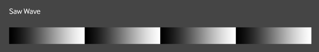
So what we’ll really start with instead is a Sine Wave texture node-set to Saw Wave. Sine/Saw Waves do generate color data, and while a sine wave oscillates between 0 and 1 (white and black), a saw wave goes 0-1, then immediately starts over at 0, giving a great visual indicator of where the gradient starts and ends.
If we just run the Sine Wave node into a Gradient node and put it into the Roughness channel of our material (where it’ll eventually end up), it’ll be annoying to try to visualize what’s going to happen. What we need is some way to just see the effects of the gradient on the material without having to disconnect any nodes or change any parameters.
Sidebar: Visualization
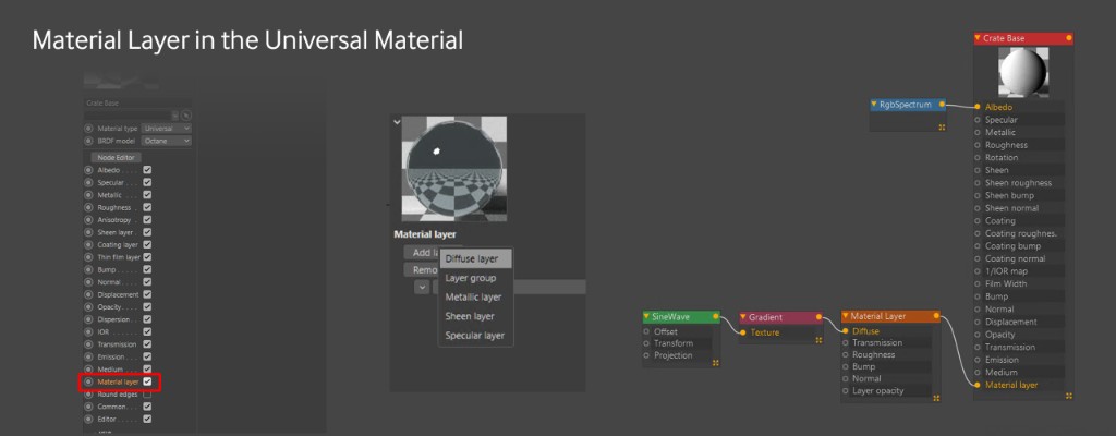
We can right-click a node and choose “solo node”. That works well in a large node chain but sometimes can cause issues in certain channels. The way we’re going to do it here is to use a Diffuse Material Layer. By default, the Material layer is disabled in the Universal Material – we need to go to the Basic tab in the node editor view, or in the Material Editor view it’s just at the bottom of all the checkboxes, and turn it on. Now the input shows up in the node editor. We can either pull a Material Layer off from the side of the node editor interface or in the Material Layer tab in the Node inspector section of the node editor, choose “Add Layer” and pick “Diffuse layer”. This will override everything in the material and we can plug our Sine Wave->Gradient chain into this and see a black and white representation of the gradient on the mesh. To get back to our original metal material, we just need to disconnect the layer and have it hang out there until we need it again.
Note: The Material Layer input on the Universal Material can only take one layer. If you need more layers, you can set the Material Layer node type to Layer Group and you’ll be able to run seven more layers into that group.
Adjusting the mask
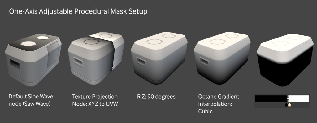
When we add the saw wave to the Diffuse layer, the result is weird because of the projection type for the texture. The Technical Deep-dive talks about this in-depth, but for now, we just need to know that most nodes in C4D default to Mesh UV projection (which we’ll use later). What we’re after here is XYZ to UVW projection. This type of projection maps the texture based on the world or object’s XYZ coordinates. This should make sense soon.
To change the projection of a texture, we need to add a Texture Projection node into the Saw Wave node. Now we can set that to XYZ to UVW and the gradient looks a little more like what we’re after, but it’s going in the wrong direction. Not an issue, we can just rotate it 90 degrees on the Z axis in the Texture Projection’s Internal Transform Section. Why Z? Because the X and Y axes didn’t do what we wanted, but Z did. So now it’s even closer to what we’re after, but there are still a few steps to go. By default, the Interpolation dropdown in the gradient node is set to Linear. The way to get a smoother black-to-white transition is to change the mode to Cubic. Now it’s pretty smooth. Finally, we can grab the handles and space them closer together, and then move both of them left to right in order to put the gradient line right on the top of the sides before it starts slanting up toward the top. Anything that’s currently black will be texture one, anything that’s currently white will be texture two, and then the small band of grays will blend the two together.
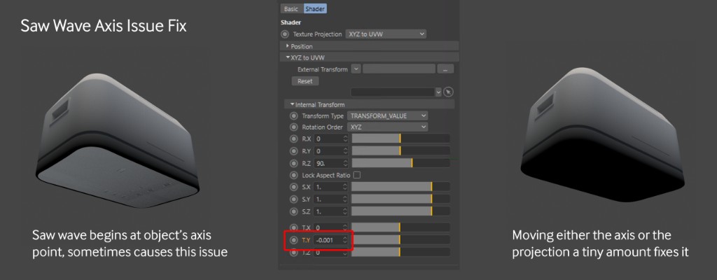
One last thing to be aware of – if we look at the underside of the crate, we’ll see something weird happening. This is because the gradient is zeroing out exactly at the anchor point of the object (which is where the saw wave starts). There are two options to fix this. Either move the anchor point down just a hair or just put a very slight negative value in the T.Y field in the Internal Transform section of the Texture Projection node. -0.001 should work. And there we go, an adjustable 1-axis quick masking system.
Mix Texture - Setup
Now that we have our mask, we can use a Mix Texture node to put together our scratch maps. This can be achieved with a Composite Texture node as well, but since it’s a simple two-part system, the Mix Texture is faster and a little cleaner for this application. We’ll continue to do this on the Diffuse Layer so we can easily see what’s happening, and then apply it to the roughness channel of our Universal Material once we’re happy with how it looks.
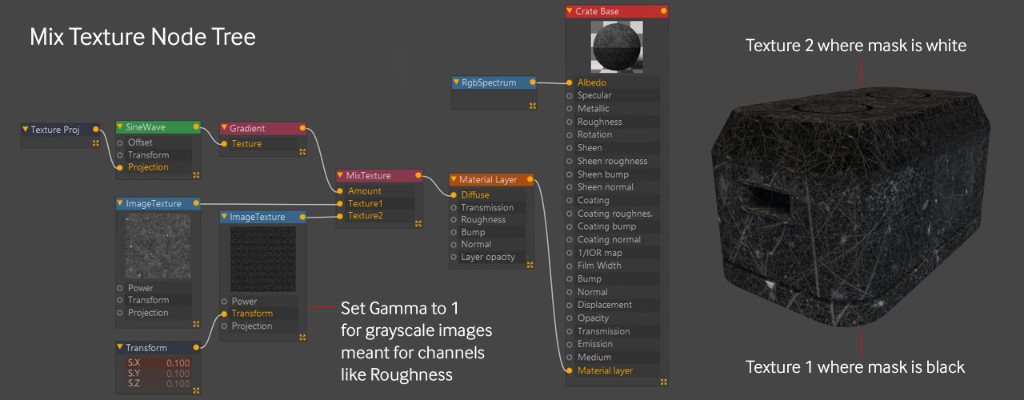
The Texture 1 input gets the really rough scratch map (CC0T Metal01_Roughness.png) so it looks like the sides took more of a beating than the top. Texture 2 gets the less intense one (CC0T Metal01-alt_Roughness.png), and then the mask that we made with the Sawtooth Wave Node which goes from black at the bottom (no contribution) to white at the top (full contribution) means that only the top bit gets the less intense scratching.
There are some other things to be aware of here. First off, these are grayscale maps meant to go into the roughness channel, which doesn’t accept color data and work in a linear color space. In order to appear properly, the Gamma needs to be set to 1 (ImageTexture gamma defaults to 2.2). Second, even though the mask we built is in the XYZ to UVW projection, each new ImageTexture node defaults to Mesh UV projection. That’s great here because the model’s UVs are set up pretty well, but if you’re working with a model with bad UVs, the projection will probably have to change. For a boxy model like this, if the UVs were bad, either Triplanar or Box projection would probably be the best bet. Lastly, the top scratches texture came in way too large – piping in a Transform node and setting the scale to 0.1 made it look better.
Mix Texture - Applying to Roughness
Let’s disconnect our Diffuse layer from the Material Layer input. If we were to just disconnect the Mix Texture from the Diffuse layer and keep it plugged in, it would continue to override the whole material with a white diffuse material. Next up, let’s disconnect the Mix Texture from the Diffuse Layer node (but leave it there in case we need it later), and pipe the Mix Texture into our roughness channel to see what it looks like.
At any point, it might help to rotate the HDRI and/or increase the intensity to get a better idea of what it’s doing on a reflective surface.

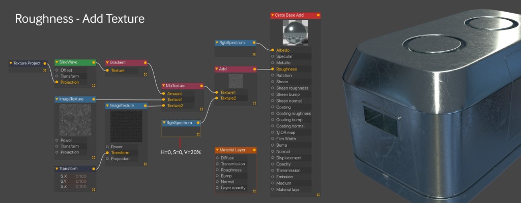
Once the texture is applied to the roughness channel, we can see it’s still a bit too shiny. To fix this, we’re going to need to combine the output of our mixed texture with white in order to brighten the whole texture up. The way we’re going to do this is with an Add node. This node blends together two textures using the Add blend mode, which will bring all of the values closer to 1 (white) and increase the roughness.
The Add node is super simple and only has two inputs. We need to run our whole tree from the Mix Texture back into the Texture 1 input, and then run another texture into the Texture 2 input to brighten it all up. We can use an RGB Spectrum node for this and start at white. Once we insert the Add node and white RGB Spectrum, we’ll see that we lost all the detail in the crate. The Add blend mode works by looking at the values of both textures and adding them together. If a pixel of texture 1 is 128 (medium gray) and the corresponding pixel of texture 2 is also 128, the add node combines them to be 256 (well, 255 which is the max), or pure white. Since the white RGB spectrum is already at 255 across the board, every pixel is already maxed out and the whole combined image is white, or 100% rough. To see any detail, we need to drag the gray value of the RGB spectrum way down.
This is easy to do in HSV mode, just drag the V (value) slider. We only need the image a bit lighter to add some overall roughness, so something like V=20% will work.
Convert to Composite Material
To make the crate look a little more beaten up, we’re going to put some wearing around the edges. This can be achieved with material layers, but it would also be a good opportunity to show off the composite material and the conversion process, so let’s do that. Let’s make a new Composite Material – it’s located in the Octane Live Viewer window under Materials, and apply the composite material to our mesh.
Important: As of the current version at this time (2020.2.1), the Composite Material requires submaterials to be used rather than standard Octane materials. We can either pull a Submaterial off the left-hand side of the node editor, or we can go into the Material 1 tab of the Composite Material in the node inspector and hit the Add Material button there. Either way, this will create a Glossy submaterial. We can then change this to a Universal Material (or almost any other type of material) in the Basic tab of the submaterial in the node inspector.
A third way of creating a submaterial, which is what we’re going to do now, is convert our already constructed blue metal material into a submaterial. Let’s get the node editor open for the new composite material we just made, and drag the metallic base material we already have from the material manager into the node graph. What we just did right now was create a link to the original material. This means if we change anything, like say change the albedo to green, it will update the original material as well, so be careful. If we try to hook that material up to the composite material node, we’ll see it doesn’t work.
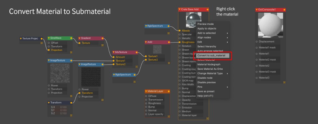
Right-click the material and choose “Convert to sub_material”. A copy of the material will appear, but at the top, the copy will say “Sub material”. This copy is no longer a link – whatever is changed here won’t affect the original material. Depending on the version of Octane you’re on, a few things might happen. In earlier versions, it would convert the material to a Diffuse type submaterial. If this is the case, you’ll need to change it back to a Universal type in the Basic tab of the material and may need to hook some of the nodes back up to the right channels. You might also still see the original material – DO NOT DELETE THIS – it’s still a live link from the original material and you’ll end up deleting the original material. If this happens, Hit the Get Active Material button in the upper left of the node editor, or just click a different material to get its node graph up, and then click the composite material again and it’ll be gone.
Your new submaterial might be hooked up to the Material 1 input. If so, great, if not, go ahead and do that manually. It’s also worth noting here that you can’t convert the submaterial back to a regular material. You can, however, copy all the nodes, make a new material of the same type, paste the nodes into the new material’s node graph, and hook them back up to the appropriate channels All those caveats out of the way, let’s move on to making some edge wear.
Edge Wear with a Material Layer
The last thing we’re going to do to the base material is add some wear. We’ll do this by adding a Metallic Submaterial and a mask into the Material 2 Mask input.
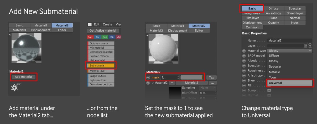
First off, let’s make a Universal Submaterial. This can be achieved by either clicking the Composite Material, going into the Node Inspector, going to the Material2 tab and hitting Add material, or by dragging Sub material from the list of nodes on the left and connecting it to the Material 2 input in the Composite Material node. If you want to get really fancy, you can also hit spacebar while the node editor is active or shift-C, and search for “sub material”.
When we hook it up, we’ll notice nothing happens. By default, the mask for that material is set to 0 (equivalent to a solid black image), which means it has no effect. To see the new submaterial, let’s set the mask to 1 (equivalent to a solid white image). Eventually we’ll override this with a mask that only affects the edges, but for now we can see what we’re doing when editing our new submaterial.
We then need to convert it to either a Metallic or Universal material. Let’s use a Universal because it would give us more options in the future if we wanted to refine the material more. We’re going to go for a realistic copper here because hey, why not.
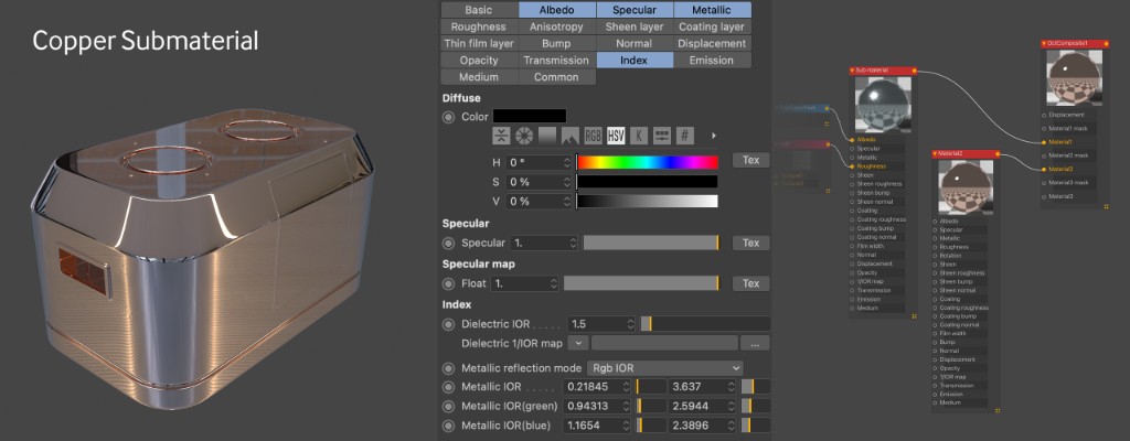
The Universal submaterial is slightly different than the standard Universal Material. The settings for Copper here are Albedo=black, Specular=0, Metallic=1. Index = RGB IOR. The values under RGB IOR are as follows: Metallic IOR: 0.21845, 3.637. Metallic IOR (green): 0.94313, 2.5944. Metallic IOR(blue): 1.1654, 2.3896. Everything else is default. Where did those numbers come from? In the Universal Material Guide, there’s an in-depth explanation of metallic IOR. It’s super nerdy but worth knowing if you’re after the most realistic metals possible. Once again it’s worth rotating the HDRI around to see what the metal will look like in various conditions. In the example above, the Power was set to 1.5, RotX is -0.25, RotY is 0.
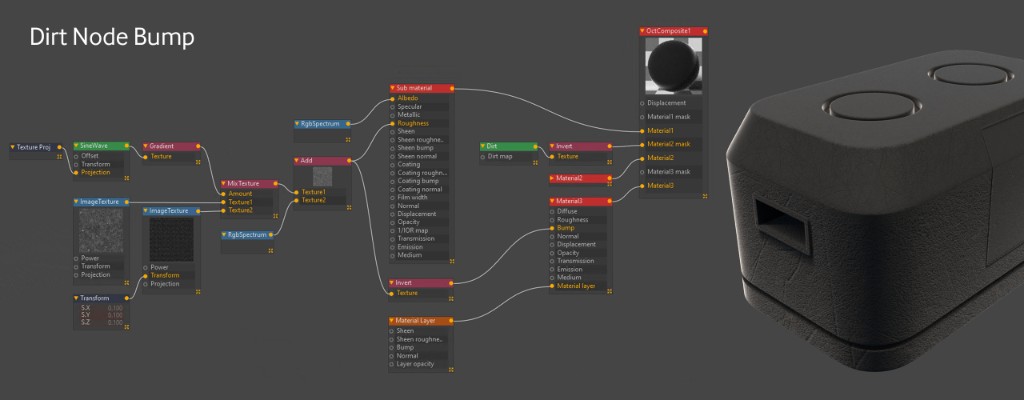
Dirt Node Mask
Time to make the mask for the copper wear. The Dirt Texture node allows you to find the edges of a model. We lost our Diffuse Material layer when we did the submaterial conversion because it wasn’t hooked up to anything. While we could just get another one and do the same thing we did before, we’re using a Composite material, so we can just make a new submaterial to test our mask out on. Using any of the methods we used before, let’s make a new submaterial, change the type to Diffuse, and then set the mask value to 1 for Material3.
Sidebar: Cleanup
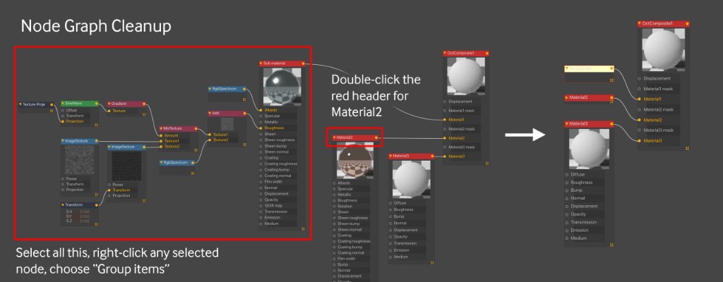
By now the node graph is starting to look a little busy. Let’s clean it up a bit so we can focus on the submaterial we’re currently working on. The first thing we can do is take everything in Submaterial 1 (the bluish metallic base) and group them all. We can do that by selecting all of the nodes associated with that material, and then right-click any one of those nodes and choosing “Group items”. This will collapse them all into a single node. To expand it back it back out, we can just right-click the group and choose “UnGroup items”.
In the case of the copper material where we don’t have any attached nodes, a quick way to minimize this is to just double-click in the red top portion where the name is and it collapses the node to just that bar. Now we can rearrange them and focus on the mask.
Back to the Dirt Node Mask
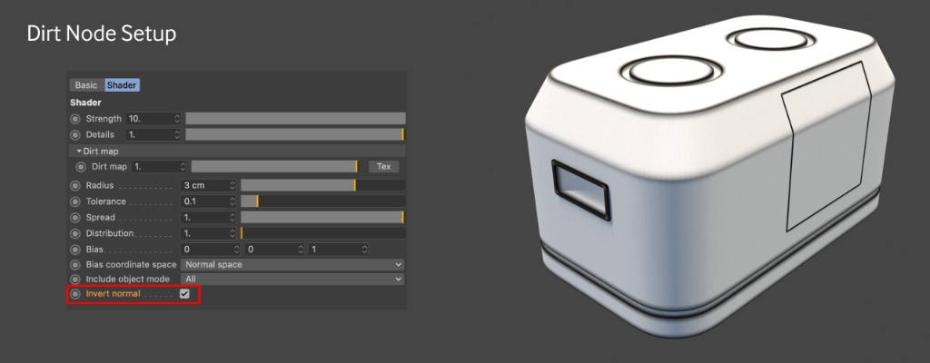
Time to pipe in a Dirt texture into the Diffuse channel of the Diffuse material. This is the same as the Albedo channel in the Universal Material if you decided to go that route.
There are a bunch of parameters to play with here, but the most important one for a mask like this is “Invert Normals”. That will amplify the effect of the edge wear. Once that’s checked, we can play with the Radius, Strength, Spread, Details and Bias to get the Mask looking how we want.
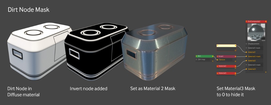
Since this is a mask for Material 2 (the copper material), the white shows where the copper will be. Right now it’s mostly white, with some black edges. We want the opposite of this – the copper should appear on the worn edges, so we’ll need to invert the mask. Pretty easy to do – just run the dirt texture node through an Invert node.
Important: When it comes time to use our dirt setup as a mask, it’s important to know that we can’t just disconnect our diffuse material from the Material 3. The Material3 Mask is still set to 1, so if we disconnected that, the material would still look like a white diffuse material. What we need to do is take the Material3 Mask value down to 0 so we can see the mixed metal materials. We’re going to leave it there and use it as a rubber bumper material for the bottom.
Rubber material for bottom
The last thing we’ll do is put a rubber-like material at the bottom. We’re going to borrow some nodes from the base material to do this. Let’s bring the Material3 Mask value back up to 1 so we can see what we’re doing.
For the Diffuse (or Albedo if you’re using the Universal Material), let’s set the color to H:0, S:0, V: 15 to get a dark gray. A rubber material has some sheen to it, so we can either convert our Diffuse Material to a Universal Material and use the Sheen channel, or we can add a sheen Material Layer to our Diffuse material. If you’re using Octane 2020.2.1 or later on Windows, you can go the Material Layer route. In earlier versions of Octane for Windows or in Octane X PR8 or earlier for MacOS, use a Universal Material for this step instead – both ways yield the same results.
Way back in the beginning of this walkthrough, we added a Material Layer to our Universal Material to previsualize the mask. Let’s do the same thing here and go to the Basic tab of the Diffuse material, and turn on the Material Layer channel. Now let’s grab a Material Layer node from the node list on the side and plug it in. In the Basic tab of the Material Layer in the node inspector, let’s change the Layer type to Sheen layer. Next let’s head over to the Sheen tab and make sure it’s set to white (full effect), and then go to the Sheen Roughness tab and set that to 0.16. If you’re going the Universal Material approach, just change the Sheen to 1 (which is the same as white), and set the Sheen Roughness in that same tab to 0.16.
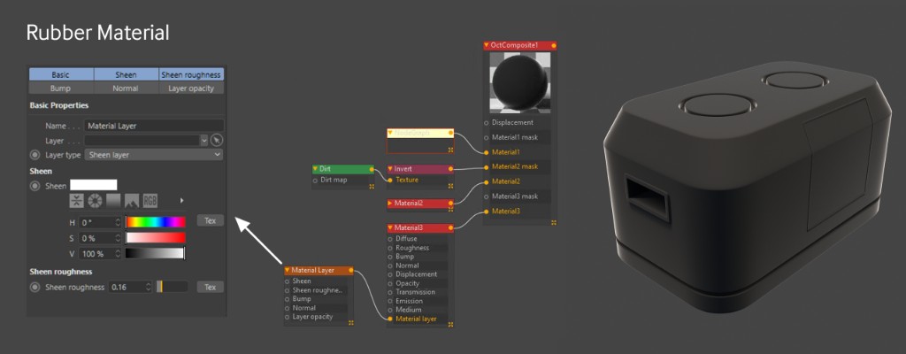
Next up let’s ungroup our base layer by right clicking the group node we made earlier and choosing UnGroup items. We want the same scratch pattern we used for the base layer on the rubber material, so we’re just going to pull another wire from that Add texture and use it in our new submaterial. Since this is a diffuse material, running it into the roughness channel won’t really do much, so let’s put it into the bump channel instead. When we run it into bump, it looks like there are raised welts on the material. To make them look like gouges instead, let’s use run it through an Invert node so the bump goes the other way.
Rubber Material Mask
Now that we’re happy with the rubber material, we’re going to want to grab the mask we already used with the adjustable gradient and use that to mask off the part at the bottom where we want the gradient. It would be possible to run the saw wave into a new gradient node, but that would make the node graph pretty messy, so let’s just duplicate the Gradient, Sine Wave and Texture Projection nodes we have by copy/pasting them and move them down near the Material 3 mask input. The beauty of our reusable gradient system here is that we can just adjust the gradient knots so the white part of the mask only covers the bottom part of the crate very quickly.
At this point we can just group up the base material again, but rather than select the Submaterial and everything before that, let’s start the group at the Add Texture material now that it’s feeding two different sources. This will make it easier to see what’s feeding what. Now all that’s left is reorging our node graph a little so it reads nicer, and then feeding the new Gradient into the Material3 Mask input, and readjusting the gradient so it’s white at the left (bottom) and black at right (top). This will only make the rubber appear at the bottom where we want it.
Conclusion
So that’s the end of part one and don’t forget to stay tuned for our part two, which will cover using a Universal Material with a UV-specific bitmap mask in the opacity channel to apply a rubber material just to the handle areas of the crate and Top Bumps. In addition, iRender also provides high-configuration machine rental service to help you save time and costs in the rendering process. iRender is a GPU-Acceleration Cloud Rendering Service for Multi-GPU Rendering with Powerful Render Nodes: 2/4/6/8x RTX 3090 provides high computing performance on the model of IaaS (Infrastructure-as-a-Service). Octane users can easily choose their machine configuration from recommended system requirements to high-end options, which suit all your project demands and will speed up your rendering process many times. iRender offers:
- Single and Multi-GPU servers: 1/2/4/6/8x RTX 3090, one of the most powerful graphic card currently available.
- 10/24 GB vRAM capacity, fitting to the heaviest images and scenes. NVLink/SLI requested for bigger vRAM.
- A RAM capacity of 128/256 GB.
- Storage (NVMe SSD): 512GB/1TB/2TB.
- Intel Xeon W-2245 or AMD Ryzen Threadripper Pro 3955WX CPU with a high clock speed of 3.90GHz.


Let’s see rendering tests with Cinema 4D and Octane, on servers 6x RTX 3090 at iRender:


Moreover, to reduce the rendering time more, users can run multiple machines at the same time. You can use the machines separately or connect them by using Thinkbox Deadline. iRender provides Redshift license, Thinkbox Deadline license for Prime customers. Users, who recharge enough points to become Prime customers, will not only be able to use Redshift/Thinkbox Deadline license without usage or maintenance costs, but also enjoy a lot of exclusive benefits.
In addition, users can request extra services to make full use of iRender servers, for example, expand image threshold, increase the size of network drive (Z:), open port, install NVLink, and change hardware. Surprisingly, you get all of these services for free.
So, do not hesitate anymore. Let’s become a member of the iRender community today to get FREE COUPON to stop wasting pointless hours of rendering. Always at the forefront of cutting-edge graphics technology, we do the rendering, the creativity is yours!
iRender – Happy Rendering!
Reference source: Scott Benson on otoy.com