
Understand Mixing and Layering Systems in Octane for C4D (part 2)
From the first part, we have covered some overall Setup of how the C4D file is constructed and pointed out where the assets originate from and Base Texture including building a Composite Material and set up a procedural mask using a Saw Wave, Gradient and Mix Texture node to tell Octane where to apply two different scratch masks.
We’ll also be using a Dirt Node to apply some edge wear, touching on grouping nodes to clean up the node graph. Finally, we reused our procedural mask to restrict a rubber material to the bottom. Now let’s come to the next part of this step though, which will continue with Masking Strategies, Handles, and Top Bumps.
Read Understand Mixing and Layering systems in Octane for C4D (part 1) in here!
Understand Mixing and Layering Systems in Octane for C4D (part 2)
Masking Strategies
We want to add a separate material for the handle, screen, bumps on top, and maybe a couple of labels for good measure. It’s possible to do all of this in the composite material we have, and it may even be a good idea to do so depending on what your plans are for the crate, but this step through exists to show you as many different paths as possible, so we’re going to take a different route. We’re going to use C4D itself as a layering system.
Polygon Selections
Understand Mixing and Layering Systems in Octane for C4D – Polygon Selection
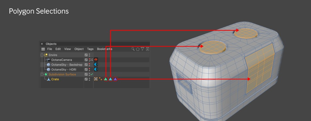
An easy way to get different materials on different portions of a model in C4D is to use Polygon selections. This involves selecting a set of polygons, and going to the Select menu and choosing Set Selection. This will create a tag on the mesh that can be renamed (and recolored if you want) and then used in a Material Tag’s Selection field to restrict the material to just those polygons. The crate model comes with three selection tags – one for each of the top bumps and one for the screen.
UV Mapping
Understand Mixing and Layering Systems in Octane for C4D – Mesh UV
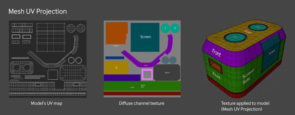
There’s a pretty good explanation of UV mapping in the Layering Systems in Octane: Technical Deep Dive document, but for now just know that all of the polygons in the crate are laid out flat on a single square called a UV map. Whatever texture is overlaying the polygons that portion of the square shows up only on those polygons on the 3D model. Building a good UV map is a somewhat complex task that requires some practice.
Model UV-Specific Bitmap Masks
Understand Mixing and Layering Systems in Octane for C4D – UV masks
Included with the assets are a set of three black and white images that can be used as masks. We’re only going to cover the handles mask in this stepthrough, but the other two are there in case you want to experiment with creating a single (probably Composite) material for the entire crate rather than the way we’re going to step through it here.
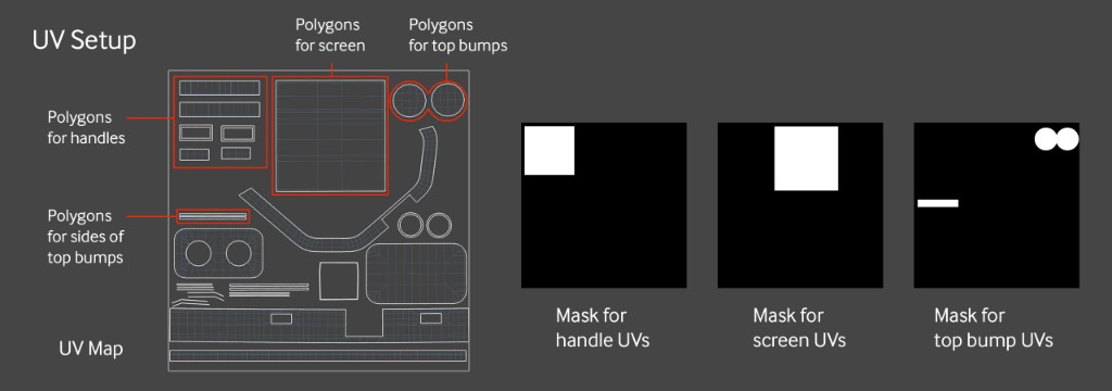
The UV set for the crate model is pretty decent, and has very distinct areas for the handles, top bumps, and screen. When making masks based on UV maps, the areas you want to mask out can be very rough as long as they don’t overlap UVs that correspond to other parts of the model.
In the model we’re dealing with, all of the handle polygons will get the same texture, but since they’re all grouped in the upper left corner and not packed in tightly with other polygons, a single, loose rectangle mask will work fine for this. Same thing with the mask for the screen – it just needs to fully cover all the UVs meant for the screen, and can overlap into the area with no other UVs without issue. The UVs for the top bumps are split across two parts of the map. So long as both areas are represented as white, the same texture or material will be applied to both parts of the model.
The Handles
We’re just going to reuse the rubber that we have already for the handles, but it’s tied up as a Submaterial in the Composite material we have. There’s no option to convert it back to a standard material, so we’ll have to move the data over manually.
Rebuilding the Rubber Material
Let’s rename our Composite Material in the Material Manager to Crate Base. Now let’s make a new Universal Material and name it. Handles. Let’s get the Crate Base material open and look at the Node graph editor. We can copy everything highlighted above from the Composite Material and paste it into the node graph of a new Universal Material. We want the submaterial also so we can easily check the values of anything we checked there.
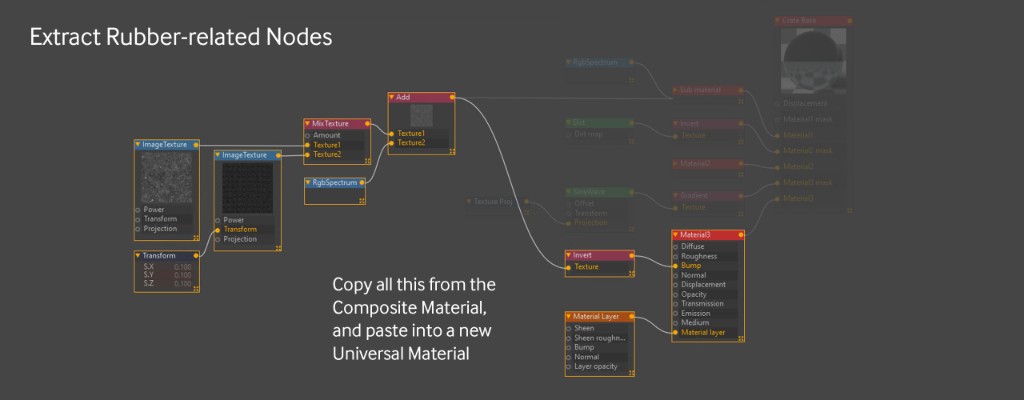
Understand Mixing and Layering Systems in Octane for C4D – Handle Material
Turns out all we need to do is match the Albedo of the Universal Material to the Diffuse value of the Diffuse submaterial, which is H:0, S:0, V:15. After that we can delete the Submaterial. Since we copied the nodes, there’s no live link back to the Composite material, so no need to worry about accidentally editing it.
In the Universal material, let’s set the Specular and Metallic values to 0 and black. In the Basic tab, turn on Material Layer, and then the Invert goes into the bump channel and the Material Layer goes into the Material Layer input, and we’ve recreated our rubber.
Rubber Opacity Mask
Understand Mixing and Layering Systems in Octane for C4D – Handle Mask
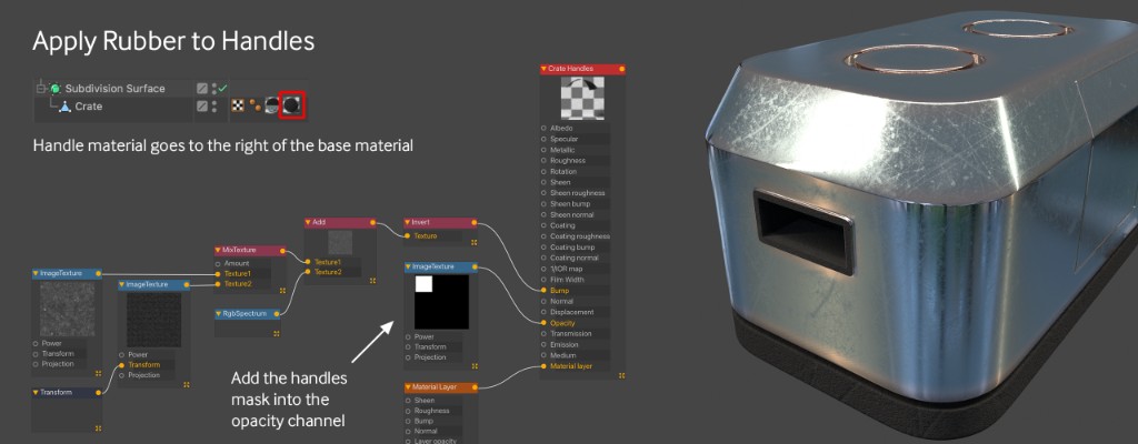
This needs to only go on the handles. To accomplish this, we can bring in an Image Texture node in and load in the Crate Mask – Handle.png image. This gets piped into the Opacity channel of the Universal Material, so now the rubber is restricted to just the box in the upper left (where it’s white in the image). Because it’s set to Mesh UV projection, that means it’s further restricted to just the polygons in that area, which as we’ve seen above, just covers the handles. The result when we put this second material on the crate mesh (to the right of the base material) is that only the handles get the rubber material.
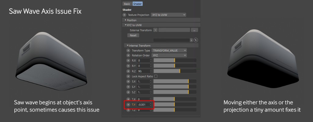
Understand Mixing and Layering Systems in Octane for C4D – Mask Fix
The Top Bumps
For the top bumps, we’re going to use a Mix material so you can see how that system works. We’re also going to use polygon selections here for the masking. There’s a UV mask image included that sections off the UVs for the top bumps in case you want to try masking them that way in a composite or layered material later, but we’re going to disregard that for this walkthrough.
Building the materials to mix
Unlike the Composite Material we used earlier that embeds all of the submaterials, the Mix material uses live links to other standard materials in the material manager. While working in the node graph for the Mix Material, any changes made to one of the linked materials will also change the original material. Before we even make a new Mix Material, we’ll need to make the materials that will feed into it.
For the glowing part, we’re going to use a simple emissive material. Let’s make a Diffuse material and add a Blackbody to the Emission channel. let’s tick the Surface Brightness checkbox and give it a power of 10 – we can adjust that later.
Next up we want to use our copper material to mix with the emissive. There aren’t any external nodes attached to our original copper submaterial, and as we know there’s no way to convert that back to a normal material at this time, so in this case it’s probably just easier to make a new Universal material. Now we just need to change the IOR to RGB IOR, and dump in the copper values (Metallic IOR: 0.21845, 3.637. Metallic IOR (green): 0.94313, 2.5944. Metallic IOR(blue): 1.1654, 2.3896.).

Understand Mixing and Layering Systems in Octane for C4D – Mix Material
Mix Material
Now we can make our Mix material and get the Node editor window up. Materials can just be dragged from the Material Manager in C4D directly into the node editor and it will create links to them. Let’s get both of our materials in, and put the copper into the Material 1 input and the emissive into the material 2 input.
The Mix material has an amount input which is essentially the mask. It comes default with a float texture (0-1 value, or you can think of it as black to white) hooked up to it. 0 would mean the mask is fully black, or that the Material 2 input has no contribution and it will just look like whatever Material 1 looks like. 1 would mean the mask is fully white, and Material 2 will completely override Material 1. The float’s default is 0.5, or 50% gray, meaning an even 50-50 blend between the two material inputs (think of it like 50% opacity in a 2D compositing app). If the float texture is deleted or disconnected, an internal 0-1 value will take over (also defaulting to 0.5) which has the same effect as the external float texture.
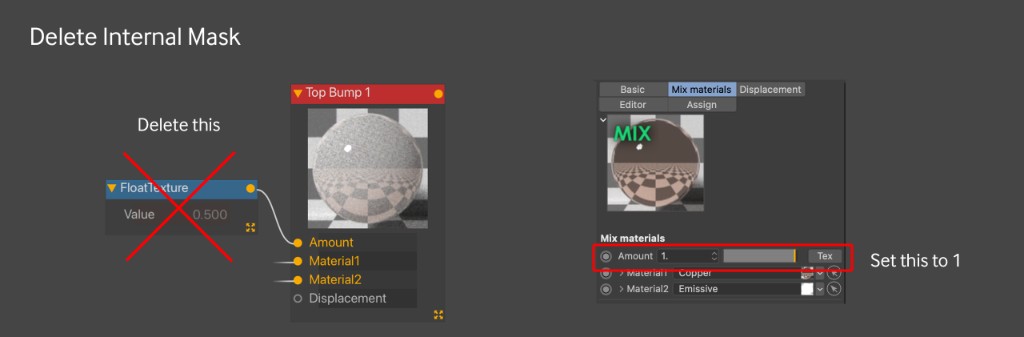
By default, we’re going to get this murky half-emissive look that we definitely don’t want. Instead, we’re going to use a custom mask, so let’s delete the float texture node and set the internal value to 1 for now so Material 2 will completely override Material 1. After we apply the material to the crate, we can work on our mask.
Applying the Mix Material to the Crate
Let’s rename the Material “Top Bump 1” and add it to the model. As expected, it takes over the entire crate. As we just learned in the Rubber material, all we’d have to do is apply the top bumps mask to the Opacity channel and it would restrict it to just the top bumps. but what if we only wanted it on one of those bumps?
One option would be to find some way to procedurally subtract from the mask in the node editor. Another is to edit the mask itself in an external app (or Bodypaint if you know it). The way we’re going to do it is by using a polygon selection to make a mask and restrict the texture to just the top bump.
Luckily (or was it planned?) the starter file for this project comes with two polygon selections already made. If you want to see what the polygon selection covers, go into Polygons mode with the crate mesh selected, then click the tag and click “Restore Selection”. This isn’t a modeling stepthrough, so we’re just going to trust that it was done right and apply it to the model.
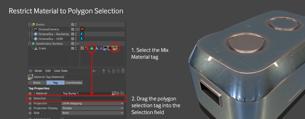
All we need to do now is select the Top Bump 1 material tag applied to the Crate mesh (not the material itself in the material manager), and then drag the first (green) polygon selection into the field that says Selection. If you just click the selection tag and release the button, the attributes for the material will be replaced by the attributes for the polygon selection, so make sure to click and drag without releasing the button.
Building the Mask
Time to get the mask going. Let’s bring in an ImageTexture node with the content-Alien Label 01.png texture in it and hook it into the Amount slider. By default it’s in Mesh UV projection, so it’s only going to overlap a few polygons on the UV map that correspond to our top bump. We know from before that we can resize the texture and move it over to line up with the correct UVs, but let’s just do this the lazy way and use XYZ to UVW projection instead (also known as flat mapping or planar mapping).
In the node inspector window for the ImageTexture node, let’s hit the projection button to get a Texture Projection node hooked up. Now let’s click the Texture projection node and set it to XYZ to UVW.
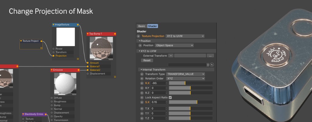
At first nothing happens. That’s because by default the texture projection node projects on the Z side (the side of our object with the screen). We want it on the top, so we’ll need to rotate it. In the Internal Transform, let’s set the R.X to -90. That will rotate it -90 degrees on the X axis and pop it up top for us. Now we can see some of the label, but we need to scale it down, so in the Internal Transform section, let’s click Lock Aspect Ratio so it scales proportionately and type in 0.15. We got lucky here and it centered up pretty good to the top bump, so we don’t have to shift it around. Since it’s projected only from the top, we don’t have to worry about it bleeding on to the sides of the bump.
Second Bump
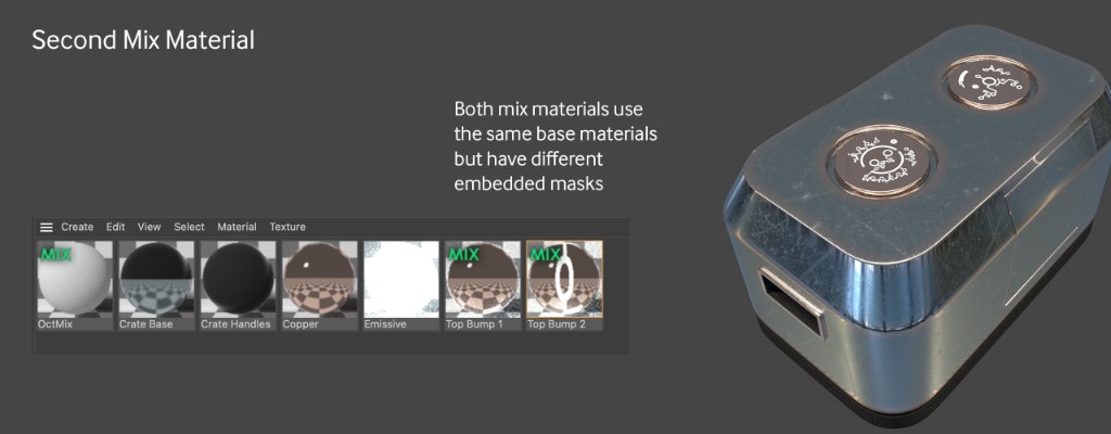
Let’s duplicate our Mix Material and rename it to Top Bump 2. Now let’s apply it to the second bump by adding it to our mesh, selecting the tag for the second mix material, and then dragging the second polygon selection tag into the Selection field.Now open our Top Bump 2 material and swap content-Alien Label 01.png for content-Alien Label 04.png. The size and projection should still hold and not affect the other material since the mask texture is embedded and not linked.
Here’s why the Mix Material is still useful in the C4D implementation of Octane. Let’s say we wanted to change the copper base to a platinum. In a Composite, Universal or Layered Material, we’d have to dig into each of the duplicated materials and change the values for the metal. In the Mix Material system, we could just change the copper material that both of the mix materials are linked to and it would update on both. This makes it easy to test out a bunch of looks in particular setups. The drawback is that you need at least three entries in the Material Manager for a Mix Material, so it can get crowded in there pretty quickly.
Conclusion
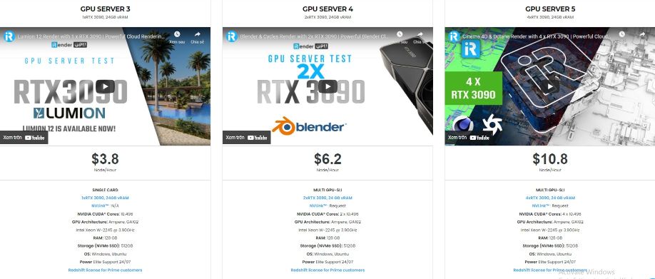
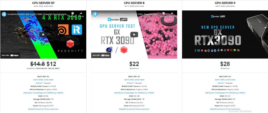
So that’s the end of part two and don’t forget to stay tuned for our final part which will cover Screen and the Label. In addition, iRender also provides high-configuration machine rental service to help you save time and costs in the rendering process. iRender is a GPU-Acceleration Cloud Rendering Service for Multi-GPU Rendering with Powerful Render Nodes: 2/4/6/8x RTX 3090 provides high computing performance on the model of IaaS (Infrastructure-as-a-Service). Octane users can easily choose their machine configuration from recommended system requirements to high-end options, which suit all your project demands and will speed up your rendering process many times. iRender offers:
- Single and Multi-GPU servers: 1/2/4/6/8x RTX 3090, one of the most powerful graphic card currently available.
- 10/24 GB vRAM capacity, fitting to the heaviest images and scenes. NVLink/SLI requested for bigger vRAM.
- A RAM capacity of 128/256 GB.
- Storage (NVMe SSD): 512GB/1TB/2TB.
- Intel Xeon W-2245 or AMD Ryzen Threadripper Pro 3955WX CPU with a high clock speed of 3.90GHz.
Let’s see rendering tests with Cinema 4D and Octane, on servers 6x RTX 3090 at iRender:


Moreover, to reduce the rendering time more, users can run multiple machines at the same time. You can use the machines separately or connect them by using Thinkbox Deadline. iRender provides Redshift license, Thinkbox Deadline license for Prime customers. Users, who recharge enough points to become Prime customers, will not only be able to use Redshift/Thinkbox Deadline license without usage or maintenance costs, but also enjoy a lot of exclusive benefits.
In addition, users can request extra services to make full use of iRender servers, for example, expand image threshold, increase the size of network drive (Z:), open port, install NVLink, and change hardware. Surprisingly, you get all of these services for free.
So, do not hesitate anymore. Let’s become a member of the iRender community today to get FREE COUPON to stop wasting pointless hours of rendering. Always at the forefront of cutting-edge graphics technology, we do the rendering, the creativity is yours!
iRender – Happy Rendering!
Reference source: Scott Benson on otoy.com