Understand Mixing and Layering Systems in Octane for Cinema 4D (part 3)
As we all know, Octane has various ways of layering textures and materials together to form complex looks and the purpose of this article is to walk you through how to use the most common ones by texturing a sci-fi crate. From the first and second parts, we have gone through almost all the steps from creating basic setups, Base Texture and Masking Strategies, etc. Now let’s come to the final part, which will guide you through Screen and Label and then see the final look of our sci-fi crate.
See more: Understand Mixing and Layering Systems in Octane for Cinema 4D (part 2)
The Screen
We’re going to look at the Layered Material for the screen. The Deep Dive goes into a lot more detail about this type of material, but it’s basically like a deconstructed Universal Material, only instead of a fixed set of channels, there are Layered Material that have groups of channels and you can arrange them any way you want in the stack to create materials that you wouldn’t otherwise be able to in the other systems.
The Layered Material doesn’t have a native alpha channel, so we’ll need to restrict it to just the screen part of the model the same way we did with the top bumps – by using the last (purple) selection tag. Let’s make a new Layered Material from the Octane LiveViewer Window under Materials.
Screen - Base Sub material
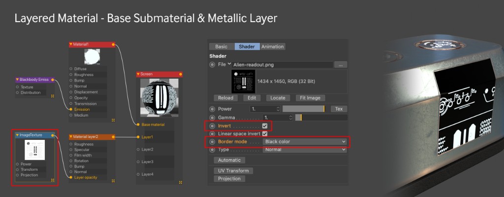
There’s currently no emission channel in any of the Material Layer types, so any emission will have to go in the base layer. Like the Composite Material we need to use a submaterial for the base material, so in the Base material tab of the Layered material, let’s hit Add Material which creates a glossy submaterial for us and connects it to the right port. A Glossy type material (or submaterial in this case) also doesn’t have an emissive channel, so in the Basic tab of the submaterial, let’s go ahead and change this to Diffuse. Now we can go into the Emission tab like we did for the bump material and add a Blackbody node. Let’s set the Power to 30 and turn on Surface Brightness.
Screen - Metallic Layer
Next up we want to put a metallic mask over the top of it. Time to get some layers going. Let’s rename our OctLayered1 material “Screen” by clicking it in the Node Editor and changing it in the Basic tab in the Node Inspector on the right. While we’re here, we’re going to want 4 more layers on top of the base material, so let’s change the number of materials to 5. Now let’s hit the Layer 1 tab, and hit the Add Layer button which becomes a dropdown, and select Metallic Layer. This will take over the whole panel, so we need to mask it out. For that, we can bring in an ImageTexture node and load in Alien-readout.png. To better visualize the mask placement, let’s make the Specular channel black.
First thing we’ll notice is that most of the screen is white, and the markings are black which is weirdly the opposite of what we see in the mask. That’s because the texture is mostly black (0, or no contribution, meaning the base material shows through which in this case is white), and only the markings part is white (1, or full contribution, meaning this is where the black material shows). We want the mask inverted, and we can do that easily in the ImageTexture node itself by checking the Invert checkbox. It’s not going to matter so much with this particular setup, but if you have a single texture, it’s usually a good idea to change the Border mode. We want a Black Color here so that anything outside the bounds of the texture is transparent.
Next thing we’ll notice that it’s cut off. This is because the ImageTexture defaults to MeshUV projection, and our readout is covering the entire UV set of the mesh. It’s only showing in the screen area because we did a polygon restriction to that area. What we need to do is scale the texture down and shift it a bit so it lines up with the screen polygons.
This is accomplished by adding a Transform node to the ImageTexture. This is found in the Node Inspector for the ImageTexture node – just hit the transform button.
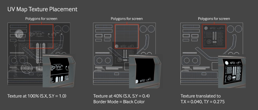
Texture Placement with Octane for Cinema 4D
After that, we just need to click the Transform node and scale it down (Lock aspect ratio on, 0.4 for S.X, S.Y and S.Z worked here), and move it around on the UV map until it’s placed properly. To sit nicely in the area designated for the screen, it needed to move a little bit over in T.X to 0.040, and a quite a bit up in T.Y to 0.275.
Most of the time you can just eyeball this by pushing the numbers around, but if you have a view of your UV map, you can estimate where you need your texture to be by thinking of 0,0 as the center of the UV map. The center point of your texture can move up to 0.5 in any direction (more than that will loop it around and be really hard to visualize). So if you need it in the bottom left corner of the map, you can start moving your T.X and T.Y values toward -0.5 and -0.5, and then fine-tune it as you start to see the image appear on the correct polygons.
Alternatively, if you have the UV map handy as an image, you can custom-build your texture in a 2D editing app to fit exactly where you want it, and then you don’t have to worry about scaling or moving around. The downside is that the texture isn’t really as reusable anymore. Let’s make our metallic layer more metallic now: Let’s set the Specular back to white, roughness to 0.25, and Thin Film Layer to Width: 0.158 and IOR: 1.68. Now it’s all shiny and pretty.
Screen - Other Layers
Now that we’re happy with the placement of the mask, we can stack on a couple of other background texture layers for variety, and then coat the whole thing with a Specular layer to make it glassy. A lot of this could be achieved just within a Universal Material, but the more complex it gets, the more custom masking needs to happen and the harder it is to tweak things, whereas with a Layered Material you’re a lot more free to move things around in groups and experiment without having to do a lot of node trickery.
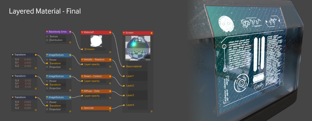
Settings for the other layers:
Layer 2: Sheen type Material Layer. Sheen Roughness: 0.75. Layer Opacity: ImageTexture with carbon fiber 01.png loaded in. Transform node into that with S.X, S.Y, S.Z = 0.4. This will give an interesting sheen effect to the carbon fiber pattern as the crate rotates. Since it’s on a material layer, this will be below the glassy specular layer.
Layer 3: Diffuse type Material Layer, all default. Layer Opacity: ImageTexture with JSplacement_dotgrid.png loaded in. Transform node into that with S.X, S.Y, S.Z = 0.125. This will put a few diffuse dots over the top of the sheen.
Layer 4: Specular type Material Layer. IOR=8. This creates a glossy topcoat over the whole thing.
The Label
The basic setup will be similar to the Handles material where it’s just a Universal Material with an Alpha channel. We don’t have a custom UV mask, and actually we’re not even 100% sure where we want it to sit, so we’ll just create it, drop it on, and move it around until it looks right. We can do this because we have a good UV set for the crate.
Setting up the Mask
Let’s make a new Universal Material and call it Label. We will work on the mask first to get the placement down, and then we can make it pretty later. We have a set of four images: content-Alien Label 03 Base. content-Alien Label 03 Symbols, content-Alien Label 03 Text and content-Alien Label 03 Outer. This would be a good place to use the new Composite Texture node to recompile them.
Composite Texture iRender with Octane for Cinema 4D
Let’s bring in all three in their own ImageTexture nodes and create a Composite Texture node also. Like the Layered Material, the Composite Texture node needs Composite Texture Layers to work. The easiest way to add those is by clicking the Composite Texture node and clicking Add Layer three times. Now we can hook each of our ImageTexture nodes to each of the layers.
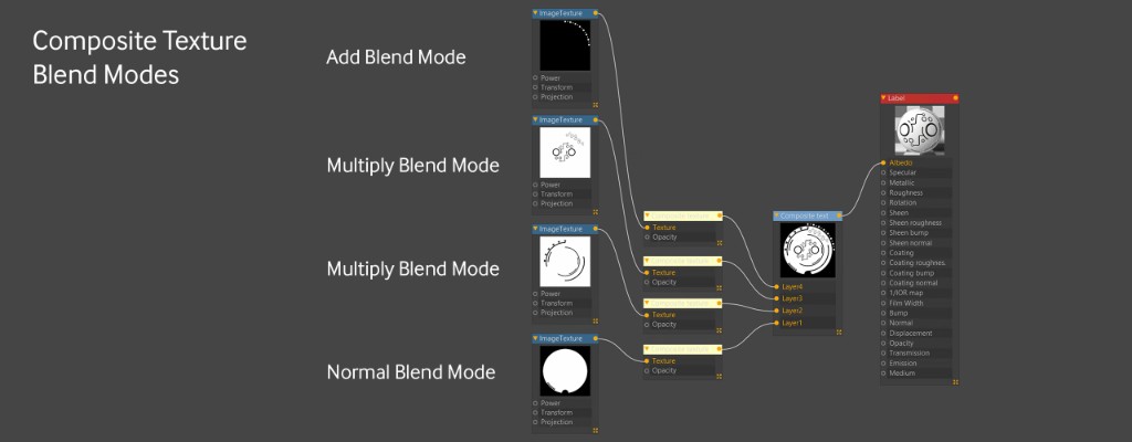
The Composite Texture works the opposite of most other mixing and layering node systems in Octane, in that it goes bottom-to-top rather than top-to-bottom. This means Layer 1 at the bottom of the stack is your “base” layer, and Layer 2 will override that, and then Layer 3 will override both Layers 1 and 2. With this in mind, let’s pipe the ImageTexture node with the Base png into the Texture slot for the Layer 1 Composite Texture Layer Node. If we enable the preview in the node (disabled by default) we can see what’s happening. The two previews should look the same.
Now let’s hook the next one up by piping the ImageTexture node with content-Alien Label 03 Symbols.png into the Texture slot for Composite Material Layer 2. This completely overrides Layer 1, so we’ll need a blend mode for this. We want to combine these textures so that the white circle remains white, but the black from the Symbols knocks ‘holes’ out of the white in the base. This is a mathematical equation, so it might be a little tricky to think it through, but let’s think about it like this: White = 1, Black = 0. If we currently have white pixels (1) and we want them to be black pixels (0), we can’t use the Add blend mode (1+0=1, so we end up with nothing happening in the circle area. We also can’t use the Subtract blend mode (1-0=1, so nothing happens here either). What we need is the Multiply blend mode. 1*0=0, so the pixels will change to black. In the areas where both are white, 1*1=1, so no change there which is what we’re after, and in the areas where both are black, 0*0=0, so no change there either which is good. Let’s set the Blend mode in Layer 2 to Multiply.
Same thing for Layer 3 (content-Alien Label 03 Text.png) – we also want the Multiply blend mode here after we hook it up to the Layer 3 texture input because we want it to do the same thing and only knock out the black areas from the textures below it.
With Layer 4 (content-Alient Label 04 Outer), we actually want anything black (0) to have no effect, and anything white (1) to turn the composite white in those areas. For this, we’ll use the Add blend mode. anything black (0) below white (1) will become white (0+1=1). Anything black will add 0 to the overall composition and won’t change anything.
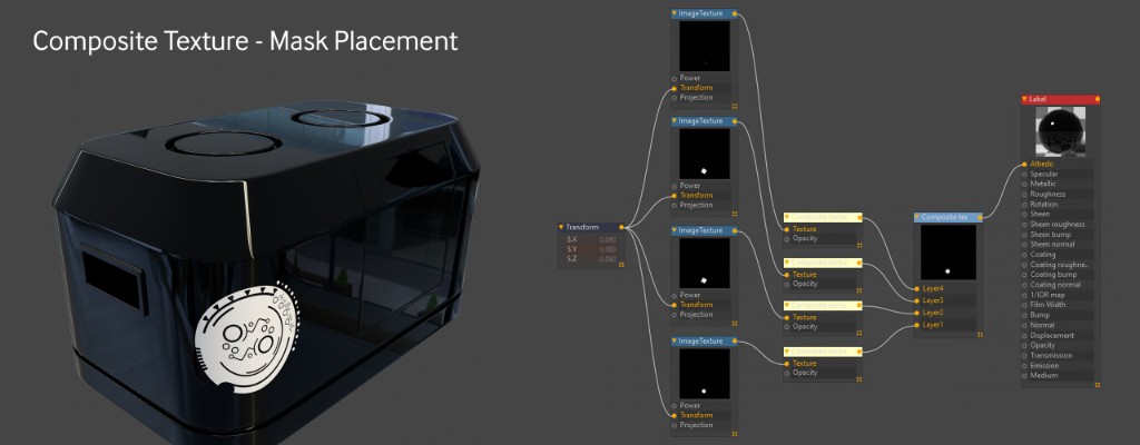
Composite Texure Mask with Octane for Cinema 4D
Now that we have the mask set up, let’s apply it to the model and see where it goes. The best way to visualize this is to take the Metallic channel of the Universal Material down to 0, and then pipe the composite material into the Albedo channel. This makes a nice high contrast material. Let’s apply it to our crate mesh.
It takes over the whole mesh as expected and repeats. Let’s deal with the repeating first. We need all four ImageTexture nodes to have the border mode set to Black color so they don’t tile.
The label needs to be scaled down to 0.08 and moved -0.017 on X and -0.346 on Y to land on the polygons that wrap around the front corner of the crate. We only need one Transform node and we can pipe it into the Transform port of each of the four images so they all do the same thing. This will take some trial and error, and it very much helps to look at the UV map again and estimate roughly where it should land first by imagining the dead center is at 0,0, the top right is at 1,1 and the bottom left is at -1,-1. The polygons that map to the front corner are in the bottom left of the UV map, so after scaling it down a lot (0.08), just nudge it a little to the left (-0.017 on X) and about a third of the way down (-0.346 on Y). Also rotate it -30 degrees on R.Z because it looks better that way.
Finishing the Label Material in Octane for Cinema 4D
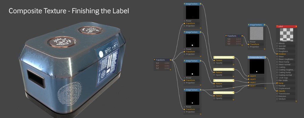
Label Material with Octane for Cinema 4D
The first thing we need to do is remove the Composite Material from the Albedo and feed it into the Opacity Channel instead. Note that due to the way the material systems work, this may cause the mix materials on the top bumps to act weird. If this happens, dragging the label material to the left of the mix materials on the mesh seems to fix it.
Now let’s bring the Metallic channel back up to 1.We’re going to want to use Anisotropy for this, so we’ll need to set the BRDF model to GGX in the Basic tab. Now we need to give it some roughness – let’s do 0.5 in the roughness channel. In the Anisotropy channel, let’s set the Anisotropy slider to 1. Then we can bring in an ImageTexture node and load in gradient_disc_overlap_output.png. That gets hooked up to the Rotation input. The image is way too large, so we need to put a Transform node on the ImageTexture node and reduce S.X, S.Y and S.Z to 0.01.
Finally, just to make it stand off the crate a little, let’s give it some bump. If we run the output of the Composite Texture into the bump channel, it gets a little too busy, so let’s just run another wire from the content-Alien Label 03 Base.png ImageTexture node and put that right into bump. That’s just enough to do the trick.
Final Touches
- A floor with a material was added to give the crate something to sit on – it’s just a simple geometric plane and the material uses an included JSPlacement texture.
- The base color was changed to #7D888A because it contrasts a little nicer.
- The Dirt Node radius was dropped to 3.
- The HDRI was desaturated using a Color Correction node. It then has to be rotated using a Transform node with T.X and T.Y (not R.X and R.Y).
- The label was given some Thin Film – R:254, G:0, B:0, IOR:1.2.
- The blackbody emissive was changed to 2000K, 50 Power.
- The sheen and albedo were darkened a bit on the rubber because it was too reflective when put on the chosen floor.
A little depth of field here, a little bloom and glare there… and it’s ready to ship some alien artifacts across the galaxy.
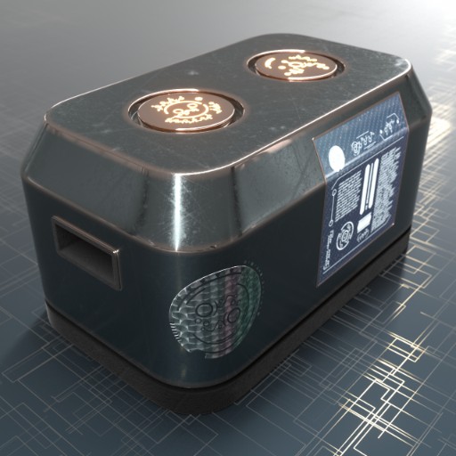
Final crate with Octane for Cinema 4D
Conclusion
This is a lot of information, but with some practice and knowing where to prioritize your effort, it should help you get you going on a good workflow which will produce faster and better renders! In conclusion, that wraps this section. Hope that with the above basic information, you could have a general overview and a better understanding of Mixing and Layering Systems in Octane for Cinema 4D.
iRender - Best Cloud Rendering for Octane Render
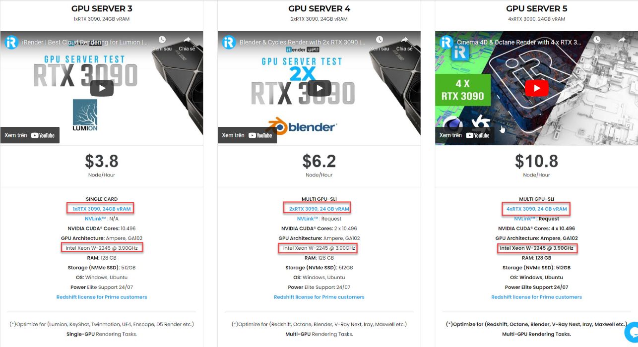
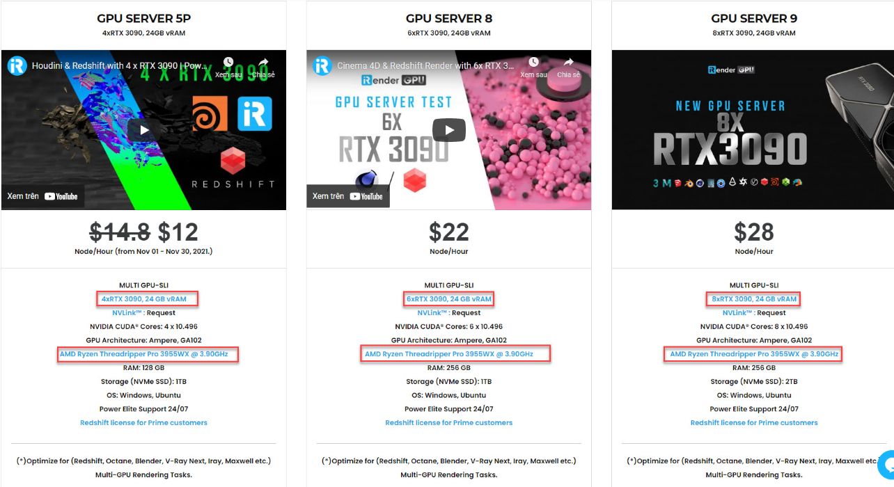
And one interesting information for you if you are having trouble choosing a suitable render farm to speed up your render time with Octane Render. Thanks to our leading technology, and with our diverse and powerful servers including servers with 1/2/4/6/8 x RTX 3090, we help Octane users create high-quality images and videos in the shortest time ever. Moreover, we offer clients the powerful processor Intel Xeon W-2245 @ 3.90GHz/AMD Ryzen Threadripper Pro 3955WX @ 3.90GHz and 512 GB – 1 TB SSD – a great option if your project requires a strong super powerful CPU. With these above powerful servers (1/2/4/6 x RTX 3090) and NVLink combined, iRender brings Octane users unprecedented rendering power, performance, and capability wherever you are!
What you need to do is just 5 simple steps including Creating an iRender account, Recharging money, Transferring your files to the remote server, Selecting a package, and connecting to the server then finally Taking full control of the server and doing whatever you want. Let’s see a rendering test with Octane project at iRender below:


Therefore, do not hesitate to become a member of the iRender community today to get FREE COUPON to stop wasting pointless hours of rendering. Always at the forefront of cutting-edge graphics technology, we do the rendering, the creativity is yours!
iRender – Happy Rendering!
Reference source: Scott Benson on otoy.com
Related Posts
The latest creative news from Octane Cloud Rendering.